 . When the cursor points to the red dot brief details will be displayed in a tooltip window. If you click on the red dot you will go to a list of all changes since this html version of the Blue Book was first made public.
World Wide Web version prepared by G. P. Moss
School of Physical and Chemical Sciences, Queen Mary University of London,
Mile End Road, London, E1 4NS, UK
g.p.moss@qmul.ac.uk
The recommendations in this version are identical to those in the published document prepared by Jonathan Brecher in Pure Appl. Chem. 2008, 80(2), 277-410. [Copyright IUPAC]. Any comments, corrections or suggestions for a future edition should be e-mailed to g.p.moss@qmul.ac.uk.
Developed by the Task Group for Graphical Representation Standards for Chemical Structure Diagrams: Chairman: W. Town (UK); Members: J. Brecher (USA), K. N. Degtyarenko (UK), H. Gottlieb (USA), R. M. Hartshorn (New Zealand), K.-H. Hellwich (Germany), J. Kahovec (Czech Republic), G. P. Moss (UK), A. McNaught (UK),J. Nyitrai (Hungary), W. Powell (USA), A. Smith (USA), K. Taylor (USA), A. Williams (USA), A. Yerin (Russia); Corresponding Members: S. Conway (UK), P. Giles (USA), M. Griffiths (USA), B. Košata (Czech Republic), B. Ramsay (USA).
Changes to the html web document have been marked by . When the cursor points to the red dot brief details will be displayed in a tooltip window. If you click on the red dot you will go to a list of all changes since this html version of the Blue Book was first made public.
Abstract: The purpose of a chemical structure diagram is to convey information — typically the identity of a molecule — to another human reader or as input to a computer program. Any form of communication, however, requires that all participants understand each other. Recommendations are provided for the display of two-dimensional chemical structure diagrams in ways that avoid ambiguity and are likely to be understood correctly by all viewers. Examples are provided in many areas, ranging from issues of typography and color selection to the relative positioning of portions of a diagram and the rotational alignment of the diagram as a whole. Explanations describe which styles are preferred and which should be avoided. Principal recommendations include:
• Know your audience: Diagrams that have a wide audience should be drawn as simply as possible.
• Avoid ambiguous drawing styles.
• Avoid inconsistent drawing styles.
CONTENTS
GR-0. INTRODUCTION
0.1 OverviewGR-1. BONDS
0.2 Presentation media
0.3 Test
0.4 Lines
0.5 Colors
0.6 Size of diagrams
GR1.1 Bond lengthsGR-2. ATOM LABELS AND OTHER CHEMICALLY SIGNIFICANT TEXT
GR1.2 Bond widths
GR1.3 Bond patterns
GR1.4 Terminal single bonds
GR1.5 Bonds with bends
GR1.6 Multiple bonds
GR1.7 Coordination bonds
GR1.8 Partial bonds
GR1.9 Multi-center bonds
GR1.10 Sidedness of double bonds
GR-2.1. Elemental atom labelsGR-3. ORIENTATION OF STRUCTURES
GR-2.2. Structural abbreviations
GR-2.3. Atom labels representing more than one non-hydrogen atom
GR-2.4. Formulas
GR-3.1. General guidelines for orientation of structuresGR-4. GR-4. POSITIONING OF SUBSTITUENTS
GR-3.2. Orientation of chains
GR-3.3. Depiction of rings
GR-3.4. Orientation of rings
GR-3.5. Positioning of double bonds in rings
GR-3.6. Structural classes with standard orientations
GR-4.1. Bond angles at chain atomsGR-5. CHARGES, UNPAIRED ELECTRONS, AND LONE PAIRS
GR-4.2. Bond angles from rings to substituents
GR-4.3. Avoidance of overlap between substituents
GR-5.1. Charges associated with specific atomsGR-6. AROMATIC RINGS AND OTHER TYPES OF ELECTRON DELOCALIZATION
GR-5.2. Lone pairs
GR-5.3. Unpaired electrons associated with specific atoms
GR-5.4. Delocalized charges and unpaired electrons
GR-5.5. Radical ions
GR-5.6. Partial charges
GR-5.7. Polyatomic ions
GR-6.1. Curves should be drawn uniformlyGR-7. SALTS AND RELATED FORMS
GR-6.2. Curves should be solid
GR-6.3. Curves represent delocalization
GR-6.4. Curves represent no more than delocalization
GR-6.5.ves should only be used when delocalization is being represented
GR-7.1.Depiction of ionic bondsGR-8. DOUBLE BONDS, DATIVE BONDS, AND CHARGE-SEPARATED FORMS
GR-7.2. Positioning of components
GR-7.3. Salts drawn in unspecified form
GR-8.1. Nitrogen compoundsGR-9. VARIABLE ATTACHMENT POINTS AND SUBSTITUENTS
GR-8.2. Phosphates and related Group V compounds
GR-8.3. Sulfoxides, sulfones, sulfimides, and related Group VI compounds
GR-9.1. Small substituentsGR-10. TAUTOMERS
GR-9.2. Predefined substituent classes
GR-9.3. Variable chain length and ring size
GR-9.4.Variable attachment location
GR-9.5. Large substituents
GR-11. ANNOTATIONS
GR-11.1.Atom-based annotationGR-12. PSEUDOBONDS
GR-11.2. Bond-based annotation
GR-11.3. Structure-based annotation
GR-12.1. Biological macromoleculesGR-13. LINEAR DRAWING STYLE
GR-12.2. Coordination polyhedra
GR-12.3. Connectors
GR-13.1. Atoms should be labeledTABLES
GR-13.2. Bonds should be sufficiently long
GR-13.3. Substituents should preferentially be upwards
GR-13.4. Structure drawing styles should be consistent
GR-13.5. Rings are always drawn as rings
I. Sample drawing styles for publicationsREFERENCES
II. Structural abbreviations
III. Common contracted atom labels
Although chemical structures have been called “the language of chemistry” [1], few documents have attempted to provide any sort of guidelines for the production of chemical structure diagrams [2–5]. The same task group that produced this document has recently published recommendations on the graphical representation of stereochemical configuration [6], but IUPAC commentary on the subject of overall graphical representation has been limited to small sections within larger documents, such as a discussion of the preferred orientation of the steroid ring system as part of the recommendations on the nomenclature of steroids [7]. In the 430-page ACS Style Guide, the chapter on “Chemical Structures” occupies only eight pages that include discussions of several topics in addition to simple representation [8]. And yet chemists have strong feelings for how chemical structure diagrams should look, even in the absence of formal guidelines. Show most chemists a series of diagrams of something as simple as benzene, and there will be near-unanimity about which ones are “good” diagrams and which ones are “bad”. As Robert Pirsig writes in Zen and the Art of Motorcycle Maintenance, “But even though Quality cannot be defined, you know what Quality is !” [9].
 |  |  | ||
 |  |  |
Production of good chemical structure depictions will likely always remain something of an art form. There are few cases where it can be said that a specific representation is “right” and that all others are “wrong” . These guidelines do not try to do that. Rather, they try to codify the sorts of general rules that most chemists understand intuitively but that have never been collected in a single printed document. Adherence to these guidelines should help produce drawings that are likely to be interpreted the same way by most chemists and, as importantly, that most chemists feel are “good-looking” diagrams.
The most important advice in any style guide is to know your audience. In the context of these recommendations, it follows that the more specific the audience for a structure, the less important it is for that structure to honor the guidelines discussed here. A structure drawn on the back of a table napkin will not be drawn with the same accuracy or precision as one that appears in a printed journal. There is nothing wrong with that. A napkin drawing has an audience of one — your colleague on the next stool — while a printed journal has a much broader audience. Similarly, the types of structures that are appropriate for the Journal of Very Specific Chemistry might not be appropriate to Chemical & Engineering News or Science or Nature.
The opposite, however, is not true. Structures drawn for a general audience can be understood without problems by a more specific one. Your colleague on the next stool can surely understand a nicely printed diagram if he or she can also understand your scribble-on-a-napkin.
Accordingly, these guidelines encourage those styles that are most likely to be understood by everyone and discourage the use of unusual, archaic, and ambiguous drawing styles.
Throughout these guidelines, you will see two recurring themes: reduction of ambiguity and proper use of context. With no context, the symbol VVVVVVVV might represent 4 tungsten atoms, 8 vanadium atoms, 17 connected carbon atoms, a wiggly bond, or a diagrammatic fracture. A simple line might represent a single bond, half of a double bond, a free valence, an iodine atom, or a negative charge. On occasion, it might even represent nothing more than a simple line itself. Context is critical. The end of one bond should not touch the end of another unless they truly are both bound to the same atom. Text should not be placed near the end of a bond unless it is intended to provide an atom label, or is so visually different from other labels (in font, size, style, color, or some combination of those) that it could not possibly be mistaken for an atom label. If you create diagrams that are difficult to interpret, you should not be surprised if people have problems interpreting them.
The same is true when creating diagrams that need to be interpreted by computer. In many ways, computers today are much more demanding than human chemists. Few programs will interpret a block of text as being an atom label, no matter how close it is to the end of a bond—unless the software is told, specifically, “That’s an atom label”. Fortunately, most software makes it easy to do so. On the other hand, software programs may let you assign specific meanings to objects that otherwise look identical, so that the symbol VVVVVVVV could be made to mean 17 connected carbon atoms without any ambiguity at all.
Whatever your audience, keep it in mind as you create your structural diagrams.
GR-0.1 Overview
The recommendations in this publication are presented approximately in the order that they should be considered by an author who is creating a chemical structure diagram. First, it is necessary to decide on basic drawing styles, including general issues such as colors and font types (GR-0). Drawing styles specific to chemical structure diagrams also need to be considered, primarily those related to the depiction of bonds (GR-1) and labeled atoms (GR-2). Once the basic styles have been chosen, the diagram itself can be produced, starting with the overall orientation of the diagram (GR-3) and continuing until all substituents have been positioned (GR-4). Other common features, including formal charges and unpaired electrons (GR-5) as well as delocalization (GR-6) have special needs that are considered separately, while the depiction of salts and related forms (GR-7) requires the relative positioning of several fragments that have been depicted individually. Various other issues are discussed in the remainder of the publication (GR-8 through the end).
Throughout this publication are numerous examples of chemical structures drawn in styles that are labeled as “preferred”, “acceptable”, “not acceptable”, or occasionally “wrong”. Due to space constraints in this document, only a few diagrams are shown for each case, with the intention that those examples are representative of the topic being discussed. The presence of one diagram labeled as “preferred” does not preclude the possibility of other “preferred” diagrams, including those with slight differences from the depicted structure in terms of bond length, line thickness, localization of double bonds in aromatic systems, or other minor details. Beyond that, it is worthwhile to clarify further the meaning of those terms as they are used here.
A chemical structure diagram is most commonly used simply as a means of identification, a way to answer the implied question, “What is the chemical structure of X ?” The styles labeled as “preferred” show how the structure should best be depicted in such cases, where there are no other overriding concerns. These depiction styles are generally applicable across many classes of chemical structures.
Sometimes, however, overriding concerns are present. Even simple structures might contain several ring systems, substituents, and functional groups. The generation of an aesthetic diagram of the whole molecule might require that individual portions are depicted in ways that would not be ideal if that portion were viewed in isolation. The diagrams labeled as “acceptable” indicate additional depiction styles that could be considered if the preferred style is inappropriate for some well-considered reason.
Many of the structural depictions included in this document are provided as counterexamples, offering clarification of how structures should not be shown. Those depictions are labeled as “not acceptable”, indicating that they should be strongly avoided in normal usage. Where possible, they have been accompanied by further description of why they are not acceptable, and why the alternative depictions are preferred or more acceptable.
Finally, a small number of examples are labeled as simply “wrong”. Those show representations that should be avoided in all cases, generally because they depict something that is either self-contradictory or because they accurately represent a molecule other than the one intended.
For the sake of readability within this paper, angular measurements of diagrams are listed with exact numerical values, such as 180°. Unless otherwise specified, all such measurements should be considered to be approximate, and specifying a range within roughly 10° of the listed value. The same applies to textual descriptions of angles, so the term “collinear” should be interpreted as “forming an angle between 170° and 190°”. In other words, two bonds that look nearly collinear should be treated as exactly collinear, even if that is not exactly true for their actual geometric relationship.
Similarly, any mention of bonds being “adjacent” or atoms being “connected to” refers to their appearance in the two-dimensional representation. Any of the four bonds of an atom with a physical (three-dimensional) tetrahedral configuration is physically adjacent to every other bond, but in a two-dimensional representation it is depicted as adjacent to only two others, and “opposite” to the third. In cyclohexane, each carbon atom is truly “connected to” four atoms: its two neighboring carbon atoms in the ring, and two external hydrogen atoms. In most diagrams, however, cyclohexane will be depicted as a regular hexagon with the hydrogen atoms implicit but not shown within the diagram. It is useful to describe those carbon atoms as being connected to only two other atoms, the two neighboring carbon atoms that are explicitly depicted. These conventions will be used throughout this publication.
The recommendations in this publication are intended for use in structural diagrams drawn in the “standard” two-dimensional format where single bonds are represented with one line segment connecting a pair of atoms, double bonds are represented with two parallel line segments connecting a pair of atoms, atoms are labeled with atomic symbols (or not shown at all in the case of carbon atoms and the hydrogen atoms bonded to them), and so on. There are other valid ways to represent structures including Newman projections, ball-and-stick models, and many others. These recommendations should not be over-generalized as applying to anything beyond the “standard” two-dimensional chemical structure diagrams.
GR-0.2 Presentation media
For the most part, these guidelines are written as in the context of a “perfect” presentation medium, where nothing will detract from the chemical structures themselves. Practical reality will rarely be that simple. Some styles that have been recommended for various printed publications are shown and contrasted in Table I, demonstrating the wide range of well-considered styles that are possible even within a single medium. When preparing diagrams for a low-resolution format such as the World Wide Web, on the other hand, it might be appropriate to make diagrams slightly larger or use a larger font than in printed journals, so that the diagrams can be read more easily on the computer screen. Presentations in printed journals have an absolute maximum width determined by the page size of that journal, and structures have to be sized and positioned accordingly. It is certainly reasonable (and altogether proper) to consider how the structures will eventually be presented and processed. There is no problem in deviating from these guidelines whenever necessary.
The prevalence of computers in chemical research provides some special problems. Compared to the number of human chemists, there are very few computer applications designed to process (display, store, search, analyze, etc.) chemical structure diagrams. Chemical structures that are likely to be interpreted by computer must be considered as having an extremely specific audience, and a fairly stupid one at that. Even the best computer programs available today are quite sensitive to the way that structures are drawn. These programs will surely become more intelligent over time, but they will not rival human intelligence in the near future. In addition to being easily interpretable by humans, structures drawn in the recommended styles are much more likely to be interpreted correctly by computers.
In some cases, no computer software currently available will be able to interpret a depiction that is otherwise completely reasonable, even preferred. We have tried to indicate those cases clearly, in sections of this document labeled with the phrase “SOFTWARE CAUTION:”, and we hope that software will evolve over time. If structures are required that must be interpreted by computers now — for example, for entry in a chemical registration system or for searching of an electronic chemical structure database — it is particularly important to understand the strengths and limitations of the software you are currently using. Again, structure drawings that follow these guidelines are more likely to be interpreted correctly than those that do not.
GR-0.3 Text
Any roman font is acceptable, but plainer fonts are preferred. Times, Times New Roman, Helvetica, and Arial are the most commonly seen serif and sans serif fonts, but that list is not exclusive. Normally, the fonts used in a chemical structure should match those used in any associated text, or be different from them in a clearly visible way (such as serif vs. sans serif).
 |  |  |  | |||
| Preferred | Preferred | Acceptable | Not acceptable |
Text should be scaled to a size that is comfortable for reading. In printed materials, that is usually in the range of 8–14 points. In other media, different sizes might be appropriate; in posters or projections, for example, a much larger size might be required. When increasing the size of text, it will usually also be necessary to increase the length of the bonds in the diagram (GR-1.1). Text that is smaller than five points in size is too small for most people to read comfortably, and is therefore not acceptable.
Formatting of text, including bold, italic, and underlined styles, should follow standard (non-chemical) style guidelines. For the most part, that means that the majority of text should be unformatted. Formatted text could be reasonably used to draw emphasis to a portion of a diagram; if emphasis is required, bold formatting is preferred over the use of italics or underlining because it provides a greater visual difference.
 |  | |
| Preferred | Not acceptable |
Within the realm of biochemical structure diagrams only, the capital P symbol has different meanings depending on whether it is roman (a phosphorus atom) or italic (an abbreviation that represents a hydroxyphosphoryl or dihydroxyphosphoryl moiety in a phosphate group [10]). Due to the long history of usage, both the roman and italic forms of the capital P must remain acceptable; however, authors should consider that the italicized version may be unfamiliar to readers who are not familiar with biochemical nomenclature. For the broadest understanding, it is preferable to depict the phosphorus-containing fragments fully with explicit atoms and bonds. It is not acceptable to create new abbreviations (see GR-2.2) whose meaning is changed by the presence or absence of text formatting.
 |  | |
| Preferred | Acceptable [for biochemical structure diagrams only |
The formatting for text should be used consistently throughout the diagram, whatever specific fonts, font sizes, and font styles are chosen. It is not acceptable to use multiple fonts and styles within a single diagram, again with intentional emphasis being an exception.
GR-0.4 Lines
Lines are most commonly used in chemical diagrams to represent bonds, but may also be used in a strictly graphical sense, for example, to divide a larger space or as the shaft of an arrow. Most lines should be drawn at a width that is consistent with the remainder of the drawing, usually close to the width of the strokes of any accompanying text. Lines that are thinner than 0.5 points should be avoided. Thicker lines should be reserved for places where emphasis is required or (when drawn as bonds) to emphasize perspective.
 |  |  | ||
| Preferred | Not acceptable | Not acceptable |
Within those general guidelines, many publications have specific preferences regarding line widths just as they often do for text (GR-0.3). When producing diagrams that are to be used by someone else, it is always recommended that authors check if there are any additional preferences that need to be followed.
GR-0.5 Colors
Except when emphasis is desired, use of color should be avoided, and chemical structures should be displayed in the same color as any associated material. Most commonly, that means that the structures should be displayed in black on a white background, although some circumstances prefer alternative coloring schemes (projected transparencies are often displayed as white or yellow on a dark blue or black background).
When emphasis is desired, colors may be used to provide that emphasis. Any colors used in a document should be clear and visually distinct. Most commonly, red would be used as the primary color for emphasis. A dark blue or dark gray color would be a very poor choice for emphasis in a structure that is mostly black, and similar choices of low-contrast color combinations should be avoided.
Authors are encouraged to remember that roughly 10 % of men are colorblind [11]. The combined use of red and green as contrasting colors in one diagram is strongly discouraged.
Authors of two-dimensional chemical diagrams should also keep in mind that there are traditional colors used for specific elements within the realm of three-dimensional modeling. Molecular models that display atoms as spheres will typically color the oxygen atoms as red, nitrogen atoms as blue, chlorine atoms as green, and so on, a coloring scheme that dates to an 1865 lecture by A. W. Hofmann where he used croquet balls in his demonstrations [12]. In current usage for molecular models, the specific shades of those colors may vary, as may the colors for less common elements. Since it is rarely necessary to color two-dimensional diagrams by element type, the traditional colors used in molecular modeling are simply not relevant in most cases. When it is desired to color two-dimensional diagrams by element type, it would be preferable to select a coloring scheme that is consistent with the traditional colors of three-dimensional modeling. It is not acceptable to color two-dimensional diagrams using color schemes that directly contradict those colors used for molecular modeling. That is, it is not acceptable to color all oxygen atoms yellow, all nitrogen atoms red, and all sulfur atoms blue within a single two-dimensional diagram.
GR-0.6 Size of diagrams
For the most part, the overall size of a structure diagram will be determined by the size chosen as the length of a standard bond and by the recommended angles between bonds in various circumstances as described in the remainder of this document. Although computers can store diagrams of any size, there are many other situations that impose restrictions on the space available for each structure diagram. In printed journals, for example, there is an absolute restriction that every structure must fit on the physical page, and the structures will often need to fit within specific column widths as well. Similarly, low-resolution media, such as the World Wide Web, may require a larger diagram overall in order to maintain legibility of fine details (see GR-0.2).
For very large, rigid molecules, there is little option but to shrink the diagram uniformly as much as necessary as to fit within the space available. When diagrams are resized, they should always be resized uniformly in both dimensions at the same time, and any associated text (such as atom labels) should be resized by the same amount.

Preferred
Acceptable
Preferred

Acceptable

Acceptable

Not acceptable
Acceptable
Not acceptable
| HO–[CH2]26–NH2 | HO[CH2]26NH2 | |
| Preferred | Acceptable | |
 |  | |
| Preferred | Not acceptable |
In most areas of chemistry, a bond represents an electronic association between two atoms. When drawing bonds, therefore, it is important to be unambiguous about (a) the nature of the electronic association — is the bond in question a single bond, double bond, or a bond of some other order — and (b) which two atoms it joins. Other types of bonding are also possible, including coordination bonds, which are discussed in GR-1.7. The use of bonds to represent configuration (e.g., using hashes and wedges) is discussed in a separate document [6].
GR-1.1 Bond lengths
Within a given structure, most bonds should be drawn using a single consistent length. The length used for bonds should be long enough so that the bond is clearly visible between two atoms or atom labels; spacing between atoms that is less than twice as long as the height of an atom label should be avoided.
 |  | |||
| Preferred | Not acceptable | Not acceptable |
 |  | |
| Preferred | Not acceptable |
 |  | |
| Preferred | Preferred |
Most bonds should be indicated with unbroken lines. The line should be approximately the same thickness as the stroke of the font used to depict atom labels in the structure (that is, the thickness of the vertical legs or the crossbar of a capital “H” in that font). Bonds that are more than four times as thick or less than one-quarter as thick as the atom label stroke width should be avoided.
 |  |  | ||
| Preferred | Not acceptable | Not acceptable |
GR-1.3 Bond patterns
Hashed, dashed, and wavy bonds should have hashes, dashes, and waves that are clearly visible and unambiguous. Typically, that means that those portions of the bond should be separated from each other by two to four times the width of a single bond, and that each bond should have at least three separate hashes, dashes, or half-waves visible. The hashes, dashes, and waves should be consistent within each bond and throughout the structure diagram.
 |  |  | ||
| Preferred | Not acceptable | Not acceptable |
GR-1.4 Terminal single bonds
As discussed in GR-2.1.2, unlabeled atoms are assumed to be carbon atoms, and so terminal single bonds are assumed to represent methyl groups. Unlabeled bonds should not be used to represent unspecified or variable attachment points (see GR-9), as such diagrams are extremely prone to misinterprFtion.
 |  |  | ||
| Preferred (for meythoxybenzene) | Acceptable (for meythoxybenzene) | Preferred (for a phenoxy substituent) |
Shorter-than-usual terminal bonds are especially problematic, as they can be confused not only with methyl groups, but also with negative charges. Bonds of this type should be strongly avoided.
Bent bonds are used exclusively in two situations, both relating to the depiction of carbohydrates. They are used when representing the glycosidic linkage between two carbohydrates drawn as Haworth projections, where the individual carbohydrate rings must remain in the horizontal orientation required by the Haworth projections. Even in such cases, it is preferable to depict the glycosidic linkage using straight bonds, with the bonds angled slightly from the vertical orientation normally required by Haworth projections. It is acceptable to depict bent bonds in such cases, but they must be drawn as smooth curves. It is not acceptable to depict bent bonds with sharp corners, since such angular bends within bonds normally imply CH2 groups, and will always present ambiguity between molecules with the normal glycosidic –O– linkage and similar analogs that truly do have a larger –CH2–O–CH2– linkage instead.
 |  | |
| Preferred | Preferred | |
 |  | |
| Acceptable | Not acceptable |
 |  |  | ||
| Preferred | Preferred | Not acceptable |
Those concerns notwithstanding, bent bonds used to indicate closures in cyclic peptides and related molecules (GR-2.2.1) must be depicted with sharp corners, since the curved forms have rarely been used and will likely be confusing to a reader unfamiliar with them.
 |  | |
| Preferred | Not acceptable |
SOFTWARE CAUTION: At the time of writing of this document, the authors know of no computer software that is able to represent bonds with smooth curves. If chemical structure diagrams of polysaccharides are required for use within an electronic environment, the use of bent bonds may indeed be not acceptable in that case. However, since there are also few examples of computer software that can properly recognize Haworth projections in any circumstance, it is most preferred to use the flat Mills diagrams (as shown in the first Preferred carbohydrate examples above) in situations where polysaccharides must be interpreted by computer software.
GR-1.6 Multiple bonds
The individual segments comprising a double (or triple, quadruple, etc.) bond should be parallel and drawn in close proximity so that the segments are clearly associated with each other and do not form separate bonds or structural fragments. For practical purposes, separations greater than 33 % of the length of the bond should be avoided.
 |  | |
| Preferred | Not acceptable |
GR-1.7 Coordination bonds
Historically, coordination bonds have been depicted in a variety of ways. Common usage now shows that such bonds are most often depicted as regular “plain” bonds. A dashed bond has also been seen, but less often.
With these recommendations, we suggest that coordination bonds be preferably represented as plain bonds. Dashed bonds are not acceptable because such bonds have been used to indicate stereochemical configurations rather than coordination.
In chemical nomenclature, coordination bonds to single atoms are named using the kappa convention, while those to contiguous atoms are named using the eta convention [13].
GR-1.7.1 Coordination bonds to single atoms
Bonds representing coordination from one atom to a single other atom should be represented as normal plain single bonds. Any hydrogen atoms bonded to the atoms at either end of such a coordination bond must be shown clearly, even if that produces a diagram where some atoms appear to have non-standard valences, such as a nitrogen atom with four attached bonds. It is not acceptable to add charges that depict formal zwitterions simply in an attempt to produce diagrams with standard valences, nor is it acceptable to depict coordination bonds by simple proximity between otherwise-unconnected fragments. The use of dative bonds to represent coordination is also not acceptable.
 |  |  | ||
| Preferred | Not acceptable | Not acceptable | ||
 |  |  | ||
| Not acceptable | Not acceptable | Not acceptable |
If a coordination bond is attached to an atom that does have a specified stereochemical configuration, then certainly a hashed or wedged bond depiction should be used instead, according to the other drawing conventions for representing configuration [6].
Coordination bonds to contiguous atoms (most commonly representing a form of π-bonding) should be drawn to indicate most clearly that special bonding pattern. Depictions that imply a regular covalent bond — and especially, depictions that show a regular covalent bond to each member of a delocalized system — are not acceptable.
 |  |  | ||
| Preferred | Not acceptable | Not acceptable |
 |  | |
| Preferred | Not acceptable |
When a coordination bond joins an atom to a contiguous system of three or more atoms, the contiguous system should be drawn using alternating single and double bonds only in those cases where it has only one such representation (as with buta-1,3-diene and related systems). Coordinated contiguous systems that can be represented by more than one pattern of single and double bonds should be depicted using curves to emphasize the coordination to the system, rather than with localized single and double bonds. This is true even if an uncoordinated analog of the same contiguous system normally would be represented with localized single and double bonds, as with the benzene system within (η6-benzene)tricarbonylchromium. The use of curves in these molecules is consistent with the preference for using curves in systems that cannot be adequately represented by alternating single and double bonds (GR-6.5).
 |  |  |  | |||
| Preferred | Preferred | Preferred | Preferred |
 |  | |
| Preferred | Acceptable |
It is not acceptable to use dashed bonds to show bonding to a delocalized system.
 |  |  |  | |||
| Not acceptable | Not acceptable | Not acceptable | Not acceptable |
GR-1.8 Partial bonds
It is often useful to depict an association between atoms that is significantly weaker than a normal covalent, coordinating, or ionic bond. The most common type of “partial bond” is a hydrogen bond, which has been defined as “a form of association between an electronegative atom and a hydrogen atom attached to a second, relatively electronegative atom” [14]. The classical hydrogen bond is considered as an electrostatic interaction between polar groups Aδ––Hδ+ and Bδ–: Aδ–––Hδ+···Bδ–.
Partial bonds should be represented with dotted lines. As with all types of bonds, dotted bonds should be long enough to be clearly visible between two atom labels, and bonds that are less than twice as long as the height of an atom label should be avoided. Dotted bonds should always include at least three dots.
 |  |  | ||
| Preferred | Preferred | Preferred |
GR-1.9 Multi-center bonds
From a molecular orbital perspective, it is possible to have bonding patterns where a pair of electrons is shared between more than two atoms. This sort of “multi-center” bonding is prevalent in the chemistry of boron compounds, for example, although it is seen in many other situations as well. As a matter of convention, any such multi-center character is ignored when producing chemical structure diagrams, and regular bonds connecting pairs of atoms are used instead.
 |  | |
| Preferred | Preferred |
In contrast with the depiction of coordination bonds (GR-1.7.2), curves should not be used when depicting multi-center bonds.
 |  | |
| Preferred | Not acceptable |
GR-1.10 Sidedness of double bonds
Double bonds traditionally appear in three orientations relative to the imaginary line connecting the centers of the atoms on either end of the bond. The double bond may be offset on either side of the center, or it may straddle the center exactly.
 |  |  |
 |  |  |
 |  |
In contrast, centered double bonds should be extended to join seamlessly with the nearest adjacent bond on either end.
If a double bond has more substituents on one side than on the other, the double bond should be offset to that side.
 |  |  | ||
| Preferred | Preferred | Preferred |
In cases where the double bond has three substituents, and the two substituents on the same end of the double bond are identical or nearly so, it is reasonable for a double bond to be drawn in a centered configuration to emphasize the local symmetry. Since a centered double bond with a single substituent on an unlabeled carbon atom may look odd, this style should only be used when the side of the double bond with one substituent has an atom label.
 |  | |
| Preferred | Preferred |
GR-1.10.2 Double bonds with two substituents on one end, and no substituents on the other
Double bonds with two or more substituents on one end and no substituents on the other should be drawn with the two segments of the double bond centered relative to its atoms. Double bonds of this type are necessarily acyclic, and are most commonly found in carbonyl and acid functional groups.
 |  |  | ||
| Preferred | Acceptable | Acceptable |
GR-1.10.3 trans-Double bonds with one substituent on each end
Double bonds with one substituent on each end, and with those two substituents trans to each other, should be drawn with one segment offset. The directionality of the offset is not prescribed for chain bonds, and may be selected by the author according to the needs of the diagram. For trans bonds that are endocyclic, the double bond should be offset toward the center of the ring (bonds of this type are uncommon).
 |  |  | ||
| Preferred | Preferred | Not acceptable | ||
 |  |  | ||
| Preferred | Not acceptable | Not acceptable |
GR-1.10.4 Double bonds with four substituents
Double bonds with two substituents on each end should normally be drawn with one segment offset. If one substituent on either end is a member of a ring, the double bond should be offset toward the center of that ring. If the double bond is a fusion bond between two rings, the bond should be offset in the direction of whichever ring has the greatest number of other double bonds. If both rings have the same number of double bonds, the double bond may be offset in either direction according to the preferences of the author.
 |  |  | ||
| Preferred | Acceptable | Acceptable | ||
 |  |  | ||
| Preferred | Preferred | Acceptable | ||
 |  |  | ||
| Preferred | Acceptable | Acceptable | ||
 |  |  | ||
| Preferred | Preferred | Acceptable |
In six-membered rings with alternating single and double bonds, it is especially preferred for the three double bonds to be offset so that they are all within the six-membered ring. That situation will usually follow as a direct consequence of offsetting the double bond toward the ring with the greatest number of other double bonds, but it would be preferable to offset the double bond toward the six-membered ring in all other cases as well.
 |  | |
| Preferred | Not acceptable |
Double bonds in acyclic systems may also be offset in either direction according to the needs of the author. It is also acceptable to draw a double bond with four substitutents in a centered configuration, but this style should be restricted to chain bonds where both substituents on one end are identical or nearly so.
 |  |  | ||
| Acceptable | Acceptable | Preferred | ||
 |  |  | ||
| Acceptable | Acceptable | Preferred |
GR-2. ATOM LABELS AND OTHER CHEMICALLY SIGNIFICANT TEXT
Textual objects serve many roles in chemical structure diagrams, but are most frequently used to represent atoms via the atomic symbols of the elements or by abbreviations that imply one or more atoms in a specified bonding pattern.
GR-2.1 Elemental atom labels
Atom labels consisting of a single non-hydrogen element are the most universally understood type of chemical information after bonds themselves. Elements are indicated by their approved element symbols [13], using proper case (the first letter of a symbol is capitalized, and subsequent ones are lower-case).
 |  | |
| Preferred | Not acceptable |
GR-2.1.1 Hydrogen atoms
If hydrogen atoms are bound directly to a labeled atom, they may be indicated directly within the atom label. A single hydrogen atom is indicated by the letter “H” immediately after the other element symbol (or before the other element symbol, for atom labels attached to the left end of a bond). Multiple hydrogen atoms are further indicated by a subscripted number following the “H”, indicating the total number of hydrogen atoms present. A labeled atom without “H” characters should be interpreted as having no hydrogen atoms attached. Such an atom might have been intended to represent a radical center or charged atom; however, it would be better to indicate the unpaired electron or charge explicitly in that case.
 |  | |
| Preferred | Preferred |
 |  |  | ||
| Wrong | Wrong | Wrong |
Under no circumstances should a labeled atom without explicitly indicated hydrogen atoms be interpreted to indicate the presence of hydrogen atoms, even if those hydrogen atoms normally would be required to satisfy normal valence rules. Rather, such an atom may only represent an atypical valence state. On the other hand, wholly unlabeled atoms represent carbon atoms with the proper number of hydrogen atoms to satisfy a valence of four.
 |  |  |  | |||
| Acceptable | Acceptable | Acceptable | Acceptable |
Carbon atoms are traditionally left unlabeled when they are bonded to at least two other atoms: the presence of the carbon atom is implied by the “bend” in the bonds.
 |  |  | ||
| Preferred | Preferred | Preferred |
On the other hand, any carbon atom with two identical collinear bonds should always be explicitly labeled, to remove the possibility of the two bonds being misinterpreted as one long bond.
 |  |  | ||
| Preferred | Preferred | Preferred |
The use of a dot in place of an explicit carbon atom label is acceptable in allenes and related molecules with three consecutive carbon atoms. It is not acceptable to use a dot to represent a carbon atom when either of its adjacent atoms is other than a carbon atom.
 |  |  | ||
| Acceptable | Not acceptable | Not acceptable |
When a dot is used to represent a carbon atom, it must be depicted clearly and unambiguously. The dot should be large enough to be clearly seen by the reader, and must be visibly separated from the adjacent bonds.
 |  | |
| Acceptable | Not acceptable |
It is not acceptable to indicate the presence of a carbon atom simply by depicting its two double bonds “on opposite sides”.
 |  |  | ||
| Not acceptable | Not acceptable | Not acceptable |
A carbon atom with no explicit bonds must always be labeled, lest it be overlooked as a stray ink smudge.
| CH4 | . | |
| Preferred | Not acceptable |
Carbon atoms attached to exactly one bond to a non-carbon atom may or may not be labeled; the labels “CH3” and “Me” may both be used, although it is not acceptable to use both “CH3” and “Me” labels within the same diagram. As discussed in GR-2.1.1, it is wrong to label a terminal carbon atom with the letter “C” when a methyl group is intended.
 |  |  | ||
| Preferred | Preferred | Acceptable |
 |  | |
| Not acceptable | Wrong |
Terminal carbon atoms should preferably also be labeled in diagrams that represent a portion of a larger structure, to eliminate any possible misinterpretation that the diagram should be attached at the unlabeled terminal carbon atom rather than at its intended connection location.
 |  |  | ||
| Preferred | Acceptable | Not acceptable |
 |  | |
| Preferred (when representing 1,3-diethylbenzene) | Wrong (when representing a 2-(3-ethylphenyl)etthyl substituent) |
It is acceptable to add labels for terminal carbon atoms connected to unlabeled carbon atoms, but only when it is possible to do so without overlapping other portions of the diagram.
 |  | |
| Preferred | Acceptable | |
 |  | |
| Preferred | Not acceptable |
When ethane, ethene, ethyne, and related molecules are drawn with only one explicit bond, both terminal carbon atoms must be labeled explicitly to prevent the molecule from being interpreted as a stray line or set of lines.
| CH3—CH3 | ||
| Preferred | Not acceptable |
GR-2.1.3 Isotopes
Isotopic substitution is indicated by a superscripted mass number appearing directly to the left of an element symbol (it is not possible to represent an isotope of an otherwise unlabeled carbon atom). The mass number should indicate the isotope’s total mass, and should not indicate its deviation from the element’s nominal mass at natural abundance.
 |  | |
| Preferred | Not acceptable |
The hydrogen isotope of mass 2 may also be indicated by the symbol “D”. The hydrogen isotope of mass 3 may also be indicated by the symbol “T”. However, the symbols “D” and “T” should preferably not be used in diagrams that also include isotopes of elements other than hydrogen.
 |  |  | ||
| Preferred | Preferred | Acceptable | ||
 |  |  | ||
| Acceptable | Preferred | Not acceptable |
The creation of atom labels containing multiple isotopes of one element should preferably be avoided, but if such a label cannot be avoided, atoms in natural abundance should be listed first, followed by other atoms in increasing isotopic mass number. If an atom label contains both deuterium and tritium, the notation style for those isotopes should be used consistently.
 |  |  |  | |||
| Preferred | Acceptable | Not acceptable | Not acceptable | |||
 |  |  |  | |||
| Acceptable | Acceptable | Not acceptable | Not acceptable |
Isotopic labeling (partial rather than complete replacement of the atom by its isotope) is indicated similarly, but the isotopically labeled atom should additionally be enclosed in square brackets. Note that only the single element symbol should be so enclosed; if there are other elements (including hydrogen atoms) described in the atom label, they should be located outside the brackets.
When required, oxidation numbers should be indicated by a superscripted roman numeral (or arabic zero) immediately following the atomic symbol. Oxidation numbers should preferably be omitted when the oxidation state is clearly indicated by the remainder of the structure, which is usually the case in diagrams that are fully specified with explicit bonds.
| Pb | Pb0 | O=Pb=O | O=PbIV=O | |||
| Preferred | Acceptable | Preferred | Acceptable |
Atom labels should be positioned so that all bonds connecting to the atom label point directly at the element symbol of the atom to which they are bonded. The bonds should approach the label closely, but should not impinge on the actual characters.
For single-character atom labels, the bonds should point to the center of the character.
 |  |  | ||
| Preferred | Preferred | Preferred | ||
 |  |  | ||
| Preferred | Preferred | Wrong | ||
 |  |  | ||
| Wrong | Wrong | Wrong |
For multiple-character atom labels, the bonds should usually point to the center of the first letter (or to the center of the last letter for atom labels attached to the left end of a bond).
 |  |  | ||
| Preferred | Not acceptable | Not acceptable |
 |  |  | ||
| Preferred | Acceptable | Not acceptable |
 |  | |
| Preferred | Not acceptable | |
 |  | |
| Preferred | Not acceptable |
GR-2.1.6 Orientation of atom labels
Atom labels should be oriented so that they avoid congestion with other portions of the structure. When the atom label consists of only a single character, this is not an issue as there are no further issues of alignment to consider. When the atom label contains several characters and there are no bonds to the right of the label, the atom label should start with the symbol of the bonded atom located at the end of a bond and the rest of the label extending to the right as shown in several of the examples above. However, when the atom label contains several characters and there are bonds to the right, aesthetic positioning is more difficult. It is quite possible for an atom label to be longer than its associated bonds. Atom labels should never be positioned so that they obscure a bond completely.
If an atom label with more than one element symbol or abbreviation has bonds to its right but does not have any bonds to its left, the atom label should be reversed.
 |  |  |  | |||
| Preferred | Not acceptable | Preferred | Not acceptable |
 |  | |
| Not acceptable | Preferred |
 |  |  | ||
| Preferred | Preferred | Preferred |
 |  | |
| Not acceptable | Not acceptable |
 |  | |
| Preferred | Not acceptable |
Atom labels with bonds both to the right and to the left may stack vertically. As above, the symbol of the bonded atom should remain positioned so that the bonds point to its center. The additional characters in the label may then be positioned on a second line either above or below the first symbol, according to whichever location has more room. Any charges, unpaired electrons, isotope mass numbers, subscripted repeat counts, etc., should remain on the same line as the associated element symbol.
The positioning and orientation of multiline atom labels is determined primarily by the orientation of bonds connected to that atom. The bond order of the bond(s) in question does not affect this determination.
Multi-line labels on atoms with fewer than two attached bonds are not acceptable.
 |  |  | ||
| Preferred | Not acceptable | Not acceptable |
 |  | |
| Preferred | Not acceptable |
 |  | |
| Preferred | Not acceptable | |
 |  | |
| Preferred | Not acceptable |
 |  |  | ||
| Preferred | Acceptable | Not acceptable |
 |  | |
| Preferred | Acceptable |
 |  |  | ||
| Preferred | Acceptable | Acceptable |
 |  |  | ||
| Preferred | Acceptable | Not acceptable |
 |  | |
| Preferred | Not acceptable |
 |  |  | ||
| Preferred | Aacceptable | Acceptable |
In addition to element symbols, atom labels may contain substituent abbreviations. The abbreviations shown in Table II may be used freely. Further definition is unnecessary.
 |  | |
| Preferred | Acceptable |
 |  | |
| Acceptable | Not acceptable |
| Abbreviation | Element name | Abbreviation full name | Meaning as abbreviation | |
| Ac | Actinium | Acetyl | Ac = |  |
| Cm | Curium | Carboxymethyl | Cm = |  |
| Nb | Niobium | p-Nitrobenzyl | Nb = |  |
| Np | Neptunium | p-Nitrophenyl | Np = |  |
| Pr | Praseodymium | Propyl | Pr = |  |
| Ts | Tennessine | Tosyl | Ts = |  |
Other than the abbreviations listed in Table GR-2.2, it is not acceptable to create new abbreviations with the same text as element symbols, even if those abbreviations are defined. Similarly, it is not acceptable to create new abbreviations with the same text (but different meaning) as other abbreviations in common use (see Table II).
 |  | |
| Not acceptable | Not acceptable |
 |  |  | ||
| Preferred | Preferred | Preferred | ||
 |  |  | ||
| Preferred | Preferred | Preferred |
Three-letter amino acid abbreviations — and other abbreviations with two or more distinct points of attachment — should also be used with care, because the nickname itself gives no indication of the intended attachment order:
Special care is needed when there might be a possibility of interpreting an abbreviation of this sort from the “wrong direction”, such as in the depiction of cyclic peptides. If a cyclic peptide is written on two lines as in the diagram below and to the right, interpreting the cyclic peptide “clockwise” requires that the Pro-Met-Asp segment be interpreted from right to left. Similarly, interpreting the cyclic peptide “counterclockwise” requires that Gln-Trp-Ala segment be interpreted from right to left. If all of the abbreviations are rigorously interpreted with their N-termini on the left, the diagram could also be interpreted as intending an unusual head-to-head and tail-to-tail coupling of the two three-peptide segments that are individually depicted horizontally. Ambiguity is inevitable with diagrams of that sort, and therefore they should be avoided. When possible, cyclic peptides should preferably be depicted in a single line, with the cycle closed by plain bonds (GR-1.5). Such problems are general to any asymmetric abbreviation and not limited to amino acids. Other issues specific to amino acids and peptides are discussed in a separate document [16].
 |  | |
| Preferred | Not acceptable |
GR-2.2.2 Single-letter abbreviations
There are many other sets of abbreviations that are used with specific molecule classes. In particular, the use of single-character abbreviations can be extremely confusing. Surely, nobody would interpret BENZENE as anything other than C6H6, but it could be Asx-Glu-Asn-Glx-Glu-Asn-Glu according to the one-letter system of amino acid nomenclature [16]. The use of single-character abbreviations should be limited to contexts where their intended meaning is clear.
It is acceptable to use the Greek lowercase letter phi (φ) to represent a phenyl group. That abbreviation has a long history, and ambiguity is unlikely since that letter is rarely used for other purposes in chemical structure diagrams.
 |  |  | ||
| Preferred | Preferred | Acceptable |
 |  |  | ||
| Preferred | Acceptable | Not acceptable [N is the single-letter abbreviation for Asn) |
When clarity is critical and space is not a concern, fully expanded structures (showing an explicit bond between every pair of non-hydrogen atoms) are always preferable to structures showing more complex atom labels. However, space often is a concern, particularly when preparing structures for publication. The following recommendations should provide some guidelines for producing complex atom labels that are likely to be understood correctly in most circumstances.
GR-2.3.1 General guidelines
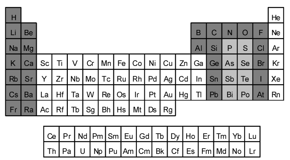
Atom labels representing more than one non-hydrogen atom — also sometimes known as “contracted” labels — rely on the fact that many elements have consistent and well-understood bonding patterns. The elements shown with a dark gray background below are fairly safe to use in contracted labels, with a few exceptions as will be discussed. The elements shown with a light gray background are less safe, as they all have common forms with several different valence states. The remaining uncolored elements have highly variable bonding patterns and should not be used in contracted labels, but always drawn with explicit bonds.
 |  |  |  | |||
| Preferred | Preferred | Preferred | Preferred | |||
 |  |  |  | |||
| Preferred | Preferred | Preferred | Preferred |
Contracted atom labels may have at most two bonds, one extending horizontally from each of the first and last characters in the label. Such labels should be read from left to right, with the first element connected to the leftmost bond and the last element connected to the rightmost bond.
 |  | |
| Preferred | Acceptable |
 |  | |
| Preferred | Not acceptable | |
 |  | |
| Preferred | Not acceptable |
Contracted atom labels attached to only one bond should be read outwards from that bond, usually from left to right if the bond is on the left of the label. If the bond is instead attached to the right of the label, the label will normally be read from right to left, but ambiguities can result. Accordingly, contracted labels with a bond on the right should be avoided except for simple cases, usually limited to relatively small labels containing four or fewer combined element symbols and abbreviations. Contracted labels with a single bond attached to an interior atom or with multiple connecting bonds should always be read from left to right, but these also are prone to ambiguity and should similarly be avoided except for simple cases.
 |  | |
| Preferred | Acceptable | |
 |  | |
| Preferred | Not acceptable |
 |  |  | ||
| Preferred | Acceptable | Not acceptable | ||
 |  |  | ||
| Preferred | Acceptable | Not acceptable |
In general, contracted labels are interpreted to fill as many valences as possible, as quickly as possible. Consider a simple case such as shown. A carbon atom is the first atom in the label, and it is connected to a single bond, so it has three remaining open valences. The next atom in the label is bromine, and is repeated three times. Bromine has one open valence, so together the three bromine atoms fill the three open valences on the carbon atom. There are no more atoms, and no open valences, so this label has been interpreted completely. This is a very simple case.
The common carboxylic acid group provides a more complex example. Again, the first carbon atom has three remaining valences. In this case, the next atom is oxygen, which has two available valences, and both of those are used to form a double bond with the carbon atom, leaving the carbon atom with one remaining valence. The third element is another oxygen, but this time only one of its valences is used to create a single bond to the carbon atom. That fills all of the available valences for the carbon atom, but leaves one remaining valence on the oxygen atom, which is in turn filled by the fourth atom, a hydrogen atom.
In the similar case of a peroxide, two valences on the first carbon atom are filled immediately by two hydrogen atoms. With only one valence remaining on the carbon atom, the first oxygen atom has no option but to chain with the second, forming a very different bonding pattern from that of the carboxylic acid.
Divalent structural fragments may be enclosed in brackets and followed by a repeat count to represent repeating fragments concisely.
As discussed above, a valence-based interpretation of atom labels will be successful only for elements with predictable bonding patterns. Some elements, including sulfur, commonly exist in a variety of valences. Contracted labels containing these elements should be avoided, particularly when those element symbols are immediately followed by multiple chalcogen or halogen symbols.
When used as part of a larger label, the textual fragments SO2, SeO2, and TeO2 should be used only to represent sulfones, selenones, and tellurones, respectively, and should never be used to represent the linear isomers or any other branching form.
Even in the presence of other atoms with variable valence, the CH2 fragment should always be interpreted as a chaining moiety, even when followed by a repeat count. Structures containing branching methylidene fragments should be drawn with explicit atoms and bonds.
CH2 fragments intended to represent branches should always be indicated with a leading equals sign and enclosed in parentheses as discussed in GR-2.3.5.
 |  |  | ||
| Preferred | Acceptable | Not acceptable | ||
 |  |  | ||
| Preferred | Acceptable | Not acceptable |
GR-2.3.5 Branching
Simple branching patterns may be implied by the basic valence rules described above, and do not require special notation. More complex branching may be clarified by placing parentheses around all elements within a branch. One valence for the first element within the parentheses is used for connecting the previous atom outside the parentheses; subsequent atoms within the parenthesized section are then bound to the first or subsequent atoms, even if an atom outside the parentheses has remaining open valences.
Branching chains where the branch is connected to the main chain by a double bond should be indicated by placing an equals sign immediately within the opening parenthesis. If desired, such labels can often be rewritten to avoid the necessity for the equals sign by swapping the text within the parentheses with the text after.
Preferred
When the only element within the parentheses is a single oxygen, sulfur, selenium, or tellurium symbol, the equals sign may be omitted
Preferred
Parentheses may be nested, but highly complex labels of this type can be extremely difficult to understand, and should be avoided.
Not acceptable
GR-2.3.6 Explicit single bonds
Explicit single bonds are generally not necessary within atom labels and should be avoided. They should be strongly avoided in contexts where they might be mistaken for negative charges. In cases where explicit single bonds are desired for clarity, it would likely be even clearer to draw the structure out fully, rather than trying to denote the single bonds inline using text.
| —CH2CH2CH3 | —CH2—CH2—CH3 | |
| Preferred | Acceptable | |
| —CH2CH2COO– | —CH2—CH2—COO– | |
| Preferred | Acceptable |
Abbreviations that contain a single attachment point may be freely used in contracted atom labels. To avoid any possible misinterpretation about whether such abbreviations truly do contain only a single attachment point, they should always appear furthest from the explicit bond within a label or within a parenthesized portion of a label.
| —CPh3 | Ph3C— | —CH2CH2CHClPh | ||
| Preferred | Preferred | Preferred |
| —CH2CH2CH(Ph)CH2CH3 | —CH2CH2CHPhCH2CH3 | |
| Preferred | Not acceptable |
If a single atom is bound to both hydrogen atoms and non-hydrogen atoms, any hydrogen atoms should be presented adjacent to the first atom, followed by the others, reading outward from the bond.
| —CHPh2 | —CPh2H | Cl2HC— | HCl2C— | |||
| Preferred | Not acceptable | Preferred | Not acceptable |
| —CBrClF | —CHBrCl | —CFBu2 | FCl2C— | Ac2HC— | ||||
| Preferred | Preferred | Preferred | Preferred | Preferred |
| —CHClCH2CH3 | —CH(CH2CH3)Cl | |
| Preferred | Not acceptable |
Atom labels are inherently ambiguous when written as simple counts of elements. The reader cannot know whether one specific isomer was intended, or whether the diagram indicates that the exact isomer truly was not known. Such labels are not acceptable; either the atoms and bonds should be drawn explicitly, or one of the alternative atom label styles discussed above should be used instead.
GR-2.4 Formulas
Formulas may be considered as atom labels not connected to any bonds. They may be preferred to structural diagrams for simple molecules such as NaCl and MeOH. Formulas should always be interpreted from left to right, but otherwise observe restrictions similar to other kinds of atom labels. For organic molecules with more than one carbon atom, structure diagrams with explicit atoms and bonds are preferred over formulas. Guidelines for producing and using formulas of inorganic molecules are presented in ref. [13].
GR-3. ORIENTATION OF STRUCTURES
When considering the guidelines to follow for the orientation of chemical structures, perhaps the most important thing to keep in mind is that, as far as chemical meaning is concerned, they do not matter. With a single exception in the case of Fischer projections [17,18], simple rotation of a chemical structure within the plane of the diagram will never affect its chemical meaning. Flipping a portion of a structure requires a corresponding adjustment of stereobonds (solid wedged bonds must be changed to hashed wedged bonds, etc.), but changes nothing otherwise. In terms of chemical meaning, the orientation of structures is irrelevant.

Selection of a reasonable orientation is an art form even more so than other aspects of structure representation. It is therefore worth emphasizing, again, that these guidelines are only guidelines. They are provided so that an author who wants to “follow the rules” has some rules to follow. They are not expected to be comprehensive for all possible chemical structures, and they are certainly not intended to be definitive. If you have a structure that you think looks better if these guidelines are not followed, then by all means draw it in the way that looks best to you. There is absolutely no problem with that.
It should also be considered that the recommendations that follow are for the depiction of chemical structure diagrams in isolation. That is, as discussed in GR-0.1, they are for use when answering the question, “What is the chemical structure of X ?” When depicting relationships between molecules, it is entirely appropriate to modify the orientation of the individual diagrams so that they accurately describe whatever relationships are being depicted. In an extreme example, ligands participating within an inorganic complex must certainly be oriented to demonstrate their role within that complex, regardless of their preferred orientation in unbound form. Similarly, reaction diagrams will often be arranged to emphasize the movement of electrons during the reaction [19]. To accomplish that, the individual reaction components may be depicted in orientations that are far from what would be preferred in isolation. When chemical structure diagrams are used in larger contexts, the diagrams may need to be modified appropriately.
GR-3.1 General guidelines for orientation of structures
GR-3.1.1 Structures should be oriented horizontally
In general, structures should be oriented so that their main axis is horizontal.

 |  | |
| Preferred | Acceptable |
 |  |  | ||
| Preferred | Acceptable | Acceptable |
Chemical structure diagrams should be oriented so that any principal groups, if present, are positioned toward the right side of the structure. In a perfect application of this guideline, principal groups would be identified using the comprehensive hierarchical guidelines provided in other IUPAC recommendations [20]. For most practical purposes, it is sufficient to treat “principal groups” and “acyclic heteroatoms” as synonymous. Thus, this rule could be oversimplified to say that any acyclic heteroatoms should be oriented toward the right side of the structure.
Since systematic numbering starts nearest the principal group(s), this guideline also implies that structures should be oriented so that systematic numbering increases from right to left within the structure.
 |  |  | ||
| Preferred | Preferred | Preferred |
 |  | |
| Preferred | Acceptable | |
 |  | |
| Preferred | Acceptable |
In the absence of a different overriding concern, the principal ring system (see GR-4.2.1) within a structure should be oriented toward the bottom-left of the structure.
 |  | |
| Preferred | Preferred |
There are two main styles for depicting acyclic structures and fragments, the “chain” (or “zigzag”) form, and the “linear” form. Since it is possible to use the linear form only for relatively simple structures, the chain form is more generally useful. The linear form, however, remains acceptable for any structure to which it is suited. Most issues that apply to the chain form would also apply to the linear form. Other issues specific to the linear form are discussed in GR-13.
GR-3.2.1 Structures should be oriented horizontally
As stated in the general overview, all structures should be oriented horizontally when possible. This is always possible for the main chain in an acyclic structure.
 |  | |
| Preferred | Preferred |
 |  |  |  | |||
| Preferred | Preferred | Preferred | Preferred |
A doubly bonded substituent that branches from a horizontal chain should preferentially be positioned above the chain rather than below it, even if that requires a change in the “zigzag direction” of the chain. This is most commonly seen in ketones, carboxylic acids, and related molecules.
 |  | |
| Preferred | Acceptable | |
 |  | |
| Preferred | Acceptable |
Unlike chains, which typically have two possible conformations at every non-terminal atom, rings have fewer degrees of freedom. It is especially important to depict rings correctly, since readers will often have firm expectations of how a ring should appear.
GR-3.3.1 Simple rings with eight or fewer ring atoms
Isolated rings that do not share any atoms with other rings should be depicted as regular polygons if they contain eight or fewer atoms within the ring.
 | ||||
| Preferred | Preferred | Preferred | ||
 |  |  | ||
| Preferred | Preferred | Preferred | ||
 |  | |||
| Not acceptable | Not acceptable | Not acceptable |
 |  |  | ||
| Preferred | Preferred (in Haworth diagrams) | Preferred (when discussng conformation) |
Isolated rings with at least nine atoms within the ring should be drawn with reentrant bond angles (“puckered”), as tracing the boundary of a properly depicted fused ring system (see GR-3.3.3).
One goal of depiction of these large rings is to preserve standard bond lengths and angles as much as possible. Ideally, every pair of standard-length bonds should be separated by 120°, but that is not even theoretically possible for rings with an odd number of atoms. If it is not possible to preserve 120° angles, it is acceptable to use other angles that are present in regular pentagons (108°), heptagons (approximately 129°), and octagons (135°).
Some examples are shown, for rings with 9 through 14 atoms. Note that there will often be more than one reasonable conformation as the rings get larger. For each ring size, the first diagram shows the preferred conformation for rings without any restrictions, such as the unsubstituted CnH2n cycloalkanes. In the presence of substituents or double bonds within the ring, it may be necessary to select one of the other conformations to avoid overlap or to preserve double-bond configuration.
| 9 atoms: |  |  | ||||||
| Preferred | Acceptable | |||||||
| 10 atoms: |  |  |  | |||||
| Preferred | Acceptable | Acceptable | ||||||
| 11 atoms: |  |  |  |  | ||||
| Preferred | Acceptable | Acceptable | Acceptable | |||||
| 12 atoms: |  |  |  |  | ||||
| Preferred | Acceptable | Acceptable | Acceptable | |||||
 |  |  | ||||||
| Acceptable | Acceptable | Acceptable | ||||||
| 13 atoms: |  |  |  | |||||
| Acceptable | Acceptable | Acceptable | ||||||
| 14 atoms: |  |  |  | |||||
| Preferred | Acceptable | Acceptable | ||||||
 |  |  | ||||||
| Acceptable | Acceptable | Not acceptable |
The single most important factor to consider when selecting a conformation is the configuration of any double bonds within the ring. Each double bond must be depicted in the correct stereochemical configuration without exception.
 |  | |
| Preferred [representing (1Z,3Z)-cyclododeca-1,3-diene] | Wrong [representing (1Z,3Z)-cyclododeca-1,3-diene] |
 |  |  |  | |||
| Preferred | Acceptable | Preferred | Not acceptable |
 |  | |
| Preferred | Acceptable | |
 |  | |
| Preferred | Acceptable |
 |  | |
| Preferred | Preferred |
 |  |  | ||
| Preferred | Acceptable | Preferred |
 |  |  | ||
| Preferred | Not acceptable | Not acceptable |
 |  | |
| Preferred | Not acceptable |
Simple fused ring systems where no atom is a member of more than two individual rings (ortho-fused but not peri-fused) should be depicted as a series of rings that are each depicted as described in GR-3.3.1 and GR-3.3.2, with the various rings abutting each other at a shared bond. All of the atoms of one ring should be placed outside of the other ring.
For aesthetic reasons, these guidelines occasionally differ from the guidelines provided in the “Nomenclature of fused and bridged fused ring systems” [21]. The orientation instructions within that document are intended for use only while determining the numbering of atoms within a fused or bridged fused ring system. The guidelines presented here should be used when depicting that ring system after its atoms have been numbered.
 |  | |
| Preferred | Preferred | |
 |  | |
| Preferred | Preferred |
 |  |  |  | |||
| Preferred | Not acceptable | Preferred | Not acceptable |
 |  |  | ||
| Preferred | Preferred | Preferred |
 |  | |
| Preferred | Not acceptable |
 |  |  |  | |||
| Preferred | Not acceptable | Preferred | Not acceptable |
 |  | |
| Preferred | Preferred |
 |  | |
| Preferred | Not acceptable |
 |  |  | ||
| Preferred | Not acceptable | Not acceptable |
 |  | |
| Preferred | Not acceptable [when representing he molecule at left] |
 |  |  | ||
| Preferred | Not acceptable | Not acceptable [representing the molecule at left] |
 |  | |
| Preferred | Not acceptable |
The depictions of bridged ring systems may be viewed as being composed of two parts: a simple ring or fused ring system, and one or more bridges that connect atoms in that simple ring or fused ring system. Viewed in this fashion, the simple ring or fused ring system should be drawn according to the recommendations for those systems, with the bridges then positioned so that they best avoid overlap and preserve legibility. For any bridged ring system, there is always more than one way to select the single/fused rings and the remaining bridges. When possible, it is preferred to select the simpler systems so as to maximize the number of undistorted six-membered rings.
As discussed in GR-3.3.3, the guidelines discussed here should be followed when producing aesthetic depictions and are not necessarily the same as those that must be followed when determining systematic names [22].
 |  |  | ||
| Preferred | Acceptable | Acceptable | ||
 |  |  | ||
| Preferred | Acceptable | Preferred |
 |  | |
| Preferred | Not acceptable |
 |  |  |  | |||
| Preferred | Not acceptable | Preferred | Not acceptable |
 |  |  | ||
| Preferred | Acceptable | Not acceptable [when representing the molecule at left] |
 |  |  |  | |||
| Preferred | Not acceptable [when representing the molecule at left] | Preferred | Not acceptable [when representing the molecule at left |
 |  |  |  | |||
| Preferred | Not acceptable | Preferred | Not acceptable |
 |  |  | ||
| Preferred | Not acceptable | Not acceptable | ||
 |  |  | ||
| Preferred | Not acceptable | Not acceptable |
 |  | |
| Preferred | Not acceptable |
SOFTWARE CAUTION: Although one hopes that no human would create diagrams with rings that exactly overlap in this manner, such overlap is regrettably common in diagrams produced by computer software. Authors are always encouraged to review the output of computer programs carefully, lest any atoms or bonds be completely obscured and the apparent meaning of a diagram be other than was intended.
 |  | |
| Preferred | Not acceptable [when representing the molecule at left] | |
 |  | |
| Preferred | Not acceptable [when representing molecule at left] |
Rings that share two bonds should preferably be arranged to minimize the distortion of both rings. Typically, that will result in both shared bonds being trans-like relative to the larger ring.
 |  |  | ||
| Preferred | Not acceptable | Not acceptable |
 |  |  | ||
| Preferred | Not acceptable | Not acceptable |
 |  | |
| Preferred | Preferred |
 |  | |
| Preferred | Preferred |
Preferred
When present, ring systems generally serve as the focal point of a chemical structure. Although there are exceptions, the “principal” ring system is normally positioned in a preferred orientation, and only then are all other substituents positioned accordingly.
GR-3.4.1 Selection of the principal ring system
In many cases — and particularly when there is only one ring system in the entire structure — selection of the principal ring system is obvious. In more complicated cases, there is substantial flexibility. Although it is always acceptable to select the principal ring system according to the hierarchy described in the “Nomenclature of fused and bridged fused ring systems“ guidelines [21], rigorous application of that hierarchy is unnecessary if the main intention is simply to produce an aesthetic diagram. For most practical purposes, it is sufficient to select the principal ring system as
• the one that has the largest number of fused rings;
• if there is more than one such system, the one with the largest individual rings (eight-membered, seven-membered, etc.);
• if there is still more than one system, the one with the greatest unsaturation; or
• if there is still more than one system, the one with the greatest number of heteroatoms
Those four guidelines are a tremendous oversimplification of the full Fused Ring Systems guidelines, but they will serve most purposes. Phrased differently, the principal ring system may be considered to be “the ring system that seems most important”. Those guidelines will usually produce the ring system that most chemists would consider to be “most important” in a structure, but they need not be followed rigorously, either. In a discussion of several related molecules, for example, it would be reasonable to select a single ring system to be considered as “most important” across the collection. So the single-ring benzoic acid might well be considered “more important” than a two-ring naphthyl group in a collection of structures that consist of 2-fluorobenzoic acid, 2-chlorobenzoic acid, 2-bromobenzoic acid, 2-hydroxybenzoic acid, 2-cyclohexylbenzoic acid, 2-(2-naphthyl)benzoic acid, etc.
Nor should the simple presence of a ring be an absolute determining factor for the orientation of a structure! In a structure with a chain that is large compared to the size of the largest ring system, it is often reasonable to treat the chain as the principal system for orienting the structure, and allow the ring(s) to be drawn as simple substitutents once the main chain is positioned.
 |  | |
| Preferred | Preferred |
Preferred
If the structure features a ring system that may be reasonably treated as a principal ring, that ring should be presented in its preferred orientation. Isolated, non-fused rings of 3, 4, 5, 7, or 8 atoms should preferentially be drawn with a horizontal bond at the bottom of the ring or the top of the ring. Isolated, non-fused six-membered rings should preferentially be drawn with a vertical bond at the left of the ring.
 |  | |||||||
| Preferred | Preferred | Preferred | Preferred | Preferred |
 |  |  |  | |||
| Preferred | Preferred | Preferred | Preferred |
 |  | |||||
| Preferred | Preferred | Preferred | Preferred |
 |  |  |  | |||||
| Preferred | Preferred | Preferred | Preferred | Preferred |
 |  |  | ||
| Preferred | Preferred | Preferred |
 |  | |
| Preferred | Preferred |
• The fused ring system is oriented more or less horizontally. A symmetry axis (or plane) should be vertical or horizontal.
• If the system contains multiple “rows” of rings, any “extra” rings should be positioned so that they are toward the right and the top of the ring system.
• Larger rings should be toward the left and smaller rings toward the right.
• Heteroatoms should be toward the right and, with slight preference, toward the bottom.
As discussed in GR-3.3.3, the guidelines discussed here should be followed when producing aesthetic depictions and should not necessarily be followed when determining systematic names.
 |  |  |  | |||
| Preferred | Preferred | Preferred | Preferred |
As discussed in GR-4.2.1, these guidelines need not be followed slavishly. According to these guidelines, a quinoline system should be drawn horizontally, with the nitrogen toward the right and, most commonly, toward the bottom. Any further substituents would be positioned with respect to that ring system, as shown below, left. In some cases, however, it is useful to emphasize some other portion of the structure. In a context where the acid group is the most interesting feature, it might be reasonable to invert the ring system to position the acid group more prominently toward the top right. Those portions of these guidelines that make sense should still be followed, however—the quinoline system should still be oriented horizontally, and not at an angle.
 |  | |
| Preferred | Preferred |
In the absence of a different overriding concern, the largest ring system within a structure should be oriented toward the bottom-left of the structure and substituents should be arranged to spread horizontally rather than vertically. Other orientations are acceptable as long as they remain legible, but those horizontal orientations tend to produce more compact diagrams that additionally are easier to interpret when included in a document with associated text that also reads horizontally.
 |  |  | ||
| Preferred | Acceptable | Acceptable |
 |  |  |  | |||
| Preferred | Acceptable | Acceptable | Acceptable |
In the general context of structure-orientation issues, the positioning of double bonds in rings is a minor issue, far less important than the positioning of the rings themselves in relation to other portions of the structure. Still, there can be a question of positioning of double bonds in rings with highly symmetric substituents (or with no substituents at all). Also, there is always a question of the cyclic positioning of double bonds within ring systems with the maximum number of non-cumulative double bonds (“mancude” ring systems), including aromatic systems. The placement of the two lines composing a double bond relative to each other is discussed in GR-1.10.4.
GR-3.5.1 Positioning of isolated double bonds
Double bonds should be positioned toward the left (and secondarily toward the top) of a ring.
 |  | |
| Preferred | Preferred |
 |  | |
| Preferred | Preferred |
In delocalized single-ring systems containing alternating single and double bonds, the bonds may be drawn in either of two resonance forms, both of which are equally preferred.
 |  | |
| Preferred | Preferred |
 |  | |
| Preferred | Preferred |
Several classes of molecules — and especially several classes of biochemical molecules — are traditionally drawn using styles that are specific to those classes. Drawing styles for those classes are illustrated within the documentation for each of those classes:
• amino acids [16]
• carbohydrates [15]
• steroids [7]
• tetrapyrroles [24]
• carotenoids [25]
• other natural products [23]
GR-4. POSITIONING OF SUBSTITUENTS
Beyond the overall orientation of structure diagrams, the relative positioning of substituents within a diagram also influences how that diagram is understood by the reader. Preservation of legibility and reduction of ambiguity continue to be of critical importance here, as in other areas of graphical representation.
GR-4.1 Bond angles at chain atoms
When chemical structures are depicted in two dimensions, they should be drawn in a way that accurately represents the true three-dimensional structures. The key word in the previous sentence is “represents”. A two-dimensional structure still remains a schematic representation, and some liberties should be taken with bond lengths, angles, etc., to produce a drawing that is most easily recognized.
Collinear bonds are of particular concern when producing two-dimensional diagrams. Two bonds should be drawn collinearly in two dimensions if and only if they connect collinearly in three dimensions, and they should be drawn at an angle in two dimensions if and only if they connect at an angle in three dimensions.
It is worth noting that the linear drawing style (GR-13) has very different rules for drawing bonds, and is considered separately.
Most atoms with two single bonds (or one single bond and one double bond) should be depicted with the bonds separated by a 120° angle. For a series of single bonds, a trans-like depiction is strongly preferred and arbitrary “bends” in the chain should be avoided without specific reason.
 |  |  | ||
| Preferred | Preferred | Preferred |
 |  |  |  | |||
| Preferred | Preferred | Preferred | Preferred |
 |  | |
| Acceptable | Not acceptable |
| F—Xe—F |  | |
| Preferred | Preferred |
 |  |  |  | |||
| Preferred | Preferred | Preferred | Preferred |
 |  | |
| Preferred | Preferred | |
 |  | |
| Preferred | Preferred |
 |  |  |  | |||
| Preferred | Preferred | Preferred | Preferred |
Atoms with three bonds drawn should almost always be depicted with three equal 120° angles separating the bonds. In this context, a double bond is considered as one “bond”, not two, and similarly for a triple bond.
Again, some exceptions exist, principally limited to configurations other than tetrahedral and trigonal planar. In a T-shaped configuration, for example, the diagram should be drawn with two of the bonds extending vertically above and below the central atom, and the third bond extending to the left.
 |  |  |  | |||
| Preferred | Preferred | Preferred | Preferred |
Atoms with four bonds may be depicted in several different ways, with a preference among these ways determined by context.
When two of the adjacent atoms are each connected to no additional atoms and two of the adjacent atoms are each connected to at least one additional atom, the four bonds should be separated by one 60° angle, an opposing 120° angle, and two 90° angles. Because of the 120° angle, this style will not disrupt the orientation of a chain in which it appears. This style also facilitates the depiction of chiral centers; the two bonds separated by the 60° angle are marked with a solid wedge and a hashed wedge. If the substituents connected to the two bonds separated by the 60° angle are not identical, the graphically larger substituent should be on the right for aesthetic purposes.
 |  |  | ||
| Preferred | Preferred | Preferred |
 |  |  |  | |||
| Preferred | Preferred | Preferred | Not acceptable |
 |  | |
| Preferred | Not acceptable | |
 |  | |
| Preferred | Not acceptable |
 |  | |
| Preferred | Acceptable | |
 |  | |
| Preferred | Acceptable |
 |  | |
| Preferred | Preferred |
 |  | |
| Preferred | Not acceptable | |
 |  | |
| Preferred | Not acceptable |
 |  | |
| Preferred | Preferred |
 |  |  | ||
| Preferred | Preferred | Not acceptable |
 |  | |
| Preferred | Acceptable | |
 |  | |
| Preferred | Acceptable |
 |  | |
| Preferred | Not acceptable |
 |  | |
| Preferred | Acceptable | |
 |  | |
| Preferred | Acceptable | |
 |  | |
| Preferred | Acceptable |
 |  |  |  |  | ||||
| Preferred | Preferred | Preferred | Preferred | Preferred |
GR-4.1.4 Atoms with more than four bonds drawn
Atoms with more than four bonds are rare in organic chemistry, but more common when dealing with inorganic complexes. If no stereochemical significance is assigned to the bonds, they should most commonly be drawn with one of the bonds directed vertically and the remainder separated by equal angles. If configuration is a concern, the bonds should be drawn in one of the recommended styles for “Graphical representation of stereochemical configuration” [6].
GR-4.1.5 Branching chains should bend outward
Unconstrained secondary chains that branch off a horizontal chain should be oriented, when possible, so that they bend outward from the graphical center of the structure diagram. Besides improving the general aesthetics of the diagram, this recommendation also helps maximize the diagram’s overall horizontal arrangement, and in many cases will also assist in emphasizing symmetry.
 |  | |
| Preferred | Acceptable | |
 |  | |
| Preferred | Acceptable |
 |  | |
| Preferred | Not acceptable | |
 |  | |
| Preferred | Wrong [when representing the (Z)-stereoisomer at left] |
In addition to the styles shown above, there is another style that may be considered when drawing double bonds in long chains when the double bonds are in a cis configuration relative to the chain. In this style, the double bond is drawn with 150° angles between it and its attached chain bonds rather than the usual 120°. This style serves to preserve the linearity of the chain, and should only be used when that is desired. It is not acceptable when there is further substitution on the double bond.
Preferred
Preferred
Preferred
Acceptable
The issues related to bond angles between ring systems and their substituents are very similar to the issues related to chain bond angles (GR-4.1). In many cases, bonds from rings to their substituents may be positioned as if the two neighboring ring bonds described a very short chain, with the substituents being placed as if they were substituents of that chain. There are additionally a few other issues to consider that are specific to rings.
GR-4.2.1 Exterior ring atoms with one substituent drawn
In most cases, exterior (non-fusion, non-bridging, non-bridgehead, non-spiro) ring atoms with a single substituent should be drawn so that the substituent bisects the larger angle formed by that atom’s two ring bonds. This is true regardless of the size of the ring or the order of the bond, and also true for non-convex rings.
 |  |  | ||
| Preferred | Preferred | Preferred |
 |  | |||||||
| Preferred | Preferred |
 |  | |
| Preferred | Acceptable | |
 |  | |
| Preferred | Acceptable |
GR-4.2.2 Fusion atoms with one substituent drawn
Ring fusion atoms already have three bonds within the ring system. For external ring fusion atoms, the substituent should preferentially be positioned outside the ring system and oriented so that it bisects the angle between the adjacent bonds.
 |  |  | ||
| Preferred | Not acceptable | Not acceptable |
 |  |  |  | |||
| Preferred | Acceptable | Preferred | Acceptable |
 |  | |
| Preferred | Not acceptable |
 |  |  | ||
| Preferred | Acceptable | Acceptable |
 |  | |
| Preferred | Acceptable |
 |  | |
| Preferred | Not acceptable |
 |  |  | ||
| Preferred | Acceptable | Not acceptable |
 |  |  | ||
| Preferred | Acceptable | Not acceptable |
 |  | |
| Preferred | Acceptable |
Ring atoms with two external bonds should normally be drawn with a 60° angle between the chain bonds. This is true regardless of the bond order of those bonds.
 |  |  |  |  | ||||
| Preferred | Preferred | Preferred | Preferred | Preferred |
 |  | |
| Preferred | Acceptable |
 |  | |
| Preferred | Preferred |
 |  |  | ||
| Preferred | Acceptable | Not acceptable | ||
 |  |  | ||
| Preferred | Acceptable | Not acceptable |
 |  | |
| Preferred | Acceptable |
 |  | |
| Preferred | Acceptable | |
 |  | |
| Preferred | Not acceptable | |
 |  | |
| Preferred | Acceptable |
If the smaller substituent can be placed on either side of the larger one, it is preferable to orient the smaller substituent so that it is exactly vertical or exactly horizontal. If neither side achieves that orientation, the smaller substituent should be oriented to the right or, if that cannot be achieved either, toward the top of the diagram.
 |  |  | ||
| Preferred | Acceptable | Acceptable |
Atoms that form a spiro union between two ring systems should normally be drawn so that the bisector of the angle between the two bonds in one ring is collinear with the similar bisector in the other ring, without distortion of either ring from the shape with which it would be depicted in the absence of the spiro union.
GR-4.2.5 Atoms with more than two substituents drawn
Ring atoms with more than two external substituents are rare in organic chemistry, but more common when dealing with inorganic complexes. If no stereochemical significance is assigned to the bonds, they should most commonly be drawn with substituents separated from each other and from the ring bonds by equal angles. If stereochemical configuration is a concern, the bonds should be drawn in one of the recommended styles for non-tetrahedral configuration [6].
GR-4.2.6 Rings drawn in perspective
Substituents on rings that have been drawn in perspective [6] should preserve the perspective of those rings. This generally means that such substituents would not be drawn to bisect the angles of the ring bonds. Some examples of substituents on rings drawn in perspective are shown.
 |  |  | ||
| Preferred | Preferred | Preferred |
While rings of eight or fewer members are most commonly drawn as convex polygons, larger rings are more appropriately drawn with some reentrant (non-convex) bond angles (see GR-4.2.2). Whenever possible, the ring should be depicted with any substituents positioned on outward-pointing atoms, so that the substituents themselves point outward according to the recommendations above.
 |  |  | ||
| Preferred | Not acceptable | Not acceptable |
 |  |
|
| Preferred | Not acceptable |
 |  |
|
| Not acceptable | Not acceptable |
 |  |
|
| Preferred | Not acceptable |
Since the clarity and legibility of a chemical structure diagram must always have priority over all else, it will often be necessary to consider alternatives to the general recommendations presented in GR-4.1 and GR-4.2 above. In particular, exact overlap between pairs of atoms or bonds is never acceptable. It is usually possible to choose among several possible approaches for avoiding such overlap. Those choices are discussed below. Furthermore, the following recommendations are presented in the order in which they should be considered. The techniques discussed in GR-4.3.2 should not be considered if overlap can be avoided completely using the recommendations of GR-4.3.1, and so on, although any single diagram may require several techniques to be applied to produce a depiction that is legible overall.
GR-4.3.1 Place a small substituent on the other side of a large substituent
For endocyclic atoms with bonds to one large substituent and one small one, GR-4.2.3 recommends that the large substituent be oriented with its bond directly outwards from the ring, and that the small substituent be positioned so that its bond bisects one of the angles adjacent to the bond to the large substituent. There are, however, two such angles. If the position normally recommended by GR-4.2.3 results in overlap that could be avoided by positioning the smaller substituent with its bond along the alternate bisector, then the alternate positioning should be chosen instead.
 |  |  | ||
| Preferred | Preferred | Not acceptable |
Rotation about a chain bond is perhaps the single most common and most useful technique for removing overlap between substituents. When there are multiple options for choosing a rotation bond, it is preferable to rotate along the bond that results in the smallest change to the overall structure diagram.
 |  |  | ||
| Preferred | Acceptable | Not acceptable |
 |  |  |  | |||
| Preferred (see GR-4.3.7) | Wrong [when representing the moleculr at left] | Wrong when representing the molecule at far left] | Not acceptable |
Positioning two large substituents adjacent to each other may result in overlap. One of those substituents should be swapped with a different adjacent substituent if doing so will produce a more legible diagram.
 |  | |
| Preferred (see GR-4.3.7) | Not acceptable | |
 |  | |
| Preferred | Not acceptable |
 |  |  | ||
| Preferred | Not acceptable | Not acceptable |
 |  |  | ||
| Preferred (see GR-4.3.8) | Acceptable | Not acceptable | ||
 |  |  | ||
| Preferred (see GR-4.3.8) | Acceptable | Not acceptable |
 |  |  | ||
| Preferred | Not acceptable | Wrong [when representing the molecule at left] |
With spiro molecules, it is common for structures to be very crowded. It is far better to distort the spiro union angle than it is to have overlapping atoms and bonds in the other parts of the structure.
 |  |  | ||
| Preferred | Preferred | Not acceptable |
When overlap is present as a result of a spiro union and cannot be avoided by distorting the spiro union angle, it may be necessary to distort the ring systems themselves. When such distortion is necessary, all ring systems should be translated outwards from the spiro atom, along with all substituents on those ring systems. This results in lengthening of the bonds to the spiro atom while leaving the other atoms and bonds unaffected.
 |  | |
| Preferred | Not acceptable [when representing the molecule at left] |
 |  | |
| Preferred | Not acceptable |
When the bonds of two six-membered rings overlap each other exactly, the simplest method to eliminate that overlap may be to change the perspective of those rings, distorting them along the axis of a substituent bond so that they become narrower and no longer overlap.
 |  | |
| Preferred | Not acceptable [when representing the molecule at left] |
 |  |  | ||
| Preferred (see GR-4.3.8) | Not acceptable | Not acceptable [when representing the molecule at left] |
After rotation along a bond (GR-4.3.1), increasing the length of a bond is the most useful single technique for avoiding overlap between substituents. Bonds may be lengthened to avoid overlap, but should not be extended further than necessary.
 |  |  | ||
| Preferred | Acceptable | Not acceptable | ||
 |  |  | ||
| Preferred | Acceptable | Not acceptable |
 |  | |
| Preferred | Preferred |
Not acceptable
 |  |  | ||
| Preferred | Acceptable | Not acceptable | ||
 |  |  | ||
| Preferred | Acceptable | Not acceptable |
 |  | |||
| Preferred | Acceptable | |||
 |  | |||
| Preferred | Not acceptable |
 |  | |
| Preferred | Acceptable |
When no other technique described above can successfully eliminate overlap and produce a legible structure diagram, it may be necessary to rotate an entire substituent.
 |  |  | ||
| Preferred | Acceptable | Not acceptable |
 |  | |
| Preferred | Not acceptable |
 |  |  |  | |||
| Preferred | Acceptable | Acceptable | Not acceptable |
 |  | |
| Preferred | Acceptable | |
 |  | |
| Preferred | Not acceptable |
When an atom has one small substituent in addition to three large substituents that are spaced more or less equally, the small substituent can bisect any of the three angles formed by the large substituents. Although the small substituent may have an orientation that is preferred in the absence of conflicts, it may be rotated to any of the three possible locations if positioning it in its preferred orientation leads to overlap that can be avoided by the rotation.
 |  |  | ||
| Preferred | Preferred | Not acceptable | ||
 |  |  | ||
| Preferred | Preferred | Not acceptable | ||
 |  |  | ||
| Preferred | Preferred | Not acceptable |
Charges, unpaired electrons, and lone pairs associated with a chemical structure may be drawn as graphical objects separate from the main structure, or as textual characters within an atom label. In real molecules, charges and unpaired electrons are often delocalized. For this reason, the delocalized charge/unpaired electron representations shown in GR-5.3 and GR-5.7 should be used when the intention is to represent the actual situation as closely as possible. In many cases, however, a localized representation is more convenient, for example, as part of a mechanistic discussion. In such cases, it is appropriate to assign the charge or unpaired electron to a specific atom as discussed in GR-5.1 and GR-5.2.
GR-5.1 Charges associated with specific atoms
Charge symbols associated with specific atoms should be positioned so that they are clearly associated with that atom and cannot be misinterpreted as being associated with some other atom. Each charge symbol should be considered as an addition to the corresponding uncharged diagram; the symbol should be placed near its associated atom in a way that best preserves the legibility of the diagram. It is generally not acceptable to modify a diagram to “make room” for a charge symbol. Charge symbols may be entered as text, by typing the appropriate characters as part of an atom label. They may also be positioned as separate objects that can be placed in positions not otherwise available when typing an atom label, such as above or below the element symbol, although it is preferable to place the charge toward the top right of its associated atom if it is possible to do so without sacrificing legibility.
A positive charge is indicated by a plus sign. When assigned to a specific atom, the plus sign should follow that atom’s element symbol. If the plus sign is entered as text (see GR-2), it should preferably be superscripted.
 |  |  | ||
| Preferred | Acceptable | Not acceptable |
 |  | |
| Preferred | Preferred |
 |  |  | ||
| Preferred | Acceptable | Not acceptable |
 |  |  |  |  | ||||
| Acceptable | Acceptable | Not acceptable | Not acceptable | Not acceptable |
 |  |  |  | |||
| Preferred | Acceptable | Preferred | Acceptable |
 |  |  |  |  | ||||
| Preferred | Not acceptable | Not acceptable | Preferred | Not acceptable |
 |  |  |  | |||
| Preferred | Preferred | Not acceptable | Not acceptable |
 |  | |
| Preferred | Preferred |
 |  | |
| Acceptable | Not acceptable |
Preferred
 |  | |
| Acceptable | Not acceptable |
Isolated lone pairs should be positioned, like unpaired electrons, close to the atom with which they are associated. They should normally be positioned exactly above, below, to the left, or to the right of the atom label, with the two dots of the lone pair parallel to the closest side (horizontally if above or below the label, vertically if to the left or the right). Positioning of lone pairs at other angles should be strongly avoided unless it is impossible to do otherwise.
 |  |  | ||
| Preferred | Preferred | Preferred |
 |  | |||
| Not acceptable | Not acceptable | Not acceptable |
GR-5.3 Unpaired electrons associated with specific atoms
The depiction of radicals is in most ways similar to the depiction of ions. An unpaired electron that is assigned to a specific atom is indicated by a dot (a “bullet” character when created on the computer). The dot should follow the atom’s element symbol, and it should also follow any hydrogen symbols associated with that atom. If the dot is entered as text, it should preferably be superscripted.
 |  |  |  |  | ||||
| Preferred | Preferred | Acceptable | Not acceptable | Not acceptable |
 |  |  |  | |||
| Preferred | Acceptable | Preferred | Acceptable |
| Preferred | Not acceptable | Not acceptable |
 |  |  | ||
| Preferred [when representing two unpaired electrons] | Preferred [when representing two unpaired electrons] | Preferred [when representing a lone pair] |
As discussed in GR-6, charges and unpaired electrons that are delocalized across several atoms should be depicted as separate graphical objects centered within the delocalized system. It is equally preferred to depict a “corner” at the top right of the diagram, with the symbol aligned with the top of the “corner” and to its immediate right.
 |  |  |  |  | ||||
| Preferred | Preferred | Acceptable | Not acceptable | Not acceptable |
Radical ions should be depicted in similar ways, with the charge symbol immediately following the dot.
 |  |  |  | |||
| Preferred | Preferred | Not acceptable | Not acceptable |
In contrast to formal charges, partial charge indicators typically represent unspecified (and usually non-integral) charge values. They are most commonly used as qualitative indicators of electronegativity or electropositivity. In general usage, partial charge indicators should be omitted from chemical structure diagrams; they should be used only when the author wishes to emphasize the partial charge distribution.
Partial charge indicators may be shown to emphasize the polar nature of certain covalent bonds, to show the charge distribution in a molecule, or to show the atoms participating in hydrogen bonds. The partial charges are designated by symbols δ– and δ+ placed near the atom in question (see GR-11). In diagrams of neutral molecules that show partial charges, at least one each of the δ– and δ+ symbols must be shown. The δ– and δ+ symbols represent unspecified “small quantities” and need not be balanced numerically even in neutral molecules.
 |  | |||
| Preferred | Preferred | Preferred |
 |  |  | ||
| Preferred | Preferred | Not acceptable |
Polyatomic ions add an additional complication. Not only do they often include coordination bonds, but any net charge is usually best represented as delocalized over the entire ion (or a large part of it).
When exact atom-and-bond connectivity is not important, an ion may be best represented by its molecular formula. In accordance with the published recommendations for the nomenclature of inorganic chemistry, the formula should be placed in square brackets, and any charge should be reported as a superscript following the rightmost bracket. For more information about the formatting of formulas, see ref. [13].
 |  | |
| Preferred | Preferred |
 |  |  |  | |||
| Not acceptable | Not acceptable | Not acceptable | Not acceptable |
GR-6. AROMATIC RINGS AND OTHER TYPES OF ELECTRON DELOCALIZATION
Standard chemical structure diagrams imply a valence-bond interpretation, with two electrons localized in the general vicinity of a single bond, four electrons near a double bond, and six electrons near a triple bond. It is well known that the physical reality is not that simple, and that many molecules exhibit significant electron mobility.
Possibly the most common class is the collection of molecules characterized as having the characteristic of aromaticity. Aromatic molecules have a cyclic π system generally containing 4n + 2 electrons, for n = 0, 1, 2, etc. Benzene is the archetypical example. Conventionally, benzene is commonly drawn with three single bonds and three double bonds, but physically, the six bonds of benzene are indistinguishable from each other. One way to depict this equivalence explicitly is to draw benzene not as a single structure but as a pair of resonance forms:

GR-6.1 Curves should be drawn uniformly
Curves should be drawn to approach all associated bonds at a consistent distance. That means, basically, that a circle should be well centered within its framework of bonds. At its closest approach, the circle should remain separated from each bond by a distance at least equivalent to the width of the bond, and no greater than twice the distance by which a double bond would be specified.
 |  |  |  | |||
| Preferred | Not acceptable | Not acceptable | Not acceptable |
 |  |  | ||
| Preferred | Preferred | Preferred |
Curves should be drawn as solid lines with the same width as a single bond.
 |  |  | ||
| Preferred | Not acceptable | Not acceptable |
Above all else, curves represent delocalization. Accordingly, they may be used to depict systems that have delocalized electrons.
 |  |  | ||||
| Preferred | Preferred | Preferred | Preferred |
 |  | |
| Preferred | Preferred |
 |  | |||||
| Preferred | Not acceptable | Preferred | Not acceptable |
 |  | |
| Preferred | Not acceptable |
 |  |  |  | |||
| Preferred | Acceptable | Preferred | Acceptable |
Curves only represent the delocalized electrons associated with their adjacent bonds. Most systems will have, at the very least, a σ framework that is not delocalized; it is this framework that is represented by the “single” bonds adjacent to the curve. Structures with additional unsaturation will need further representation. For example, a depiction of the delocalized form of didehydrobenzene would have a “double” bond replacing one of the “single” bonds.
 |  | ||
| Preferred | Acceptable |
Curves represent delocalization, yet lots of structures have some delocalized elements. Although all such elements could be depicted with curves, there is little gained by doing so. On the contrary, the arbitrary use of curves can draw the viewer’s attention to insignificant portions of a structural diagram, and away from areas that are chemically more important such as an active site or a reactive group. Accordingly, curves should only be used when the delocalization is specifically being highlighted as an important feature of the structure.
When curves are not used, any alternating configuration of double bonds is acceptable within the further constraints discussed in GR-3.5.
 |  |  | ||
| Preferred | Preferred | Acceptable |
 |  |  |  | |||
| Preferred | Not acceptable | Not acceptable | Not acceptable |
 |  | |
| Preferred | Wrong |
Salts are characterized by having more than one component, most commonly with one or more cationic components accompanied by one or more anionic component. Although such components are physically associated by ionic bonds, they are traditionally depicted on paper as separate, disjoint fragments. So, in addition to all the issues involved with drawing each individual fragment, salts should also be drawn with a consideration of how those fragments should be positioned in relation to each other.
It should be noted that although salts consist of cationic and anionic components, they are not always drawn with explicit charges. Many pharmaceuticals, for example, are isolated as hydrochloride salts. It is often reasonable — and, when the site of protonation is variable or uncertain, unavoidable &mdsh; to draw such molecules with a neutral parent structure and a neutral hydrogen chloride.
Some molecules may be formally drawn with positive and negative charges within a single structural fragment. The discussion here is limited to compounds that are or could be depicted using multiple fragments.
GR-7.1 Depiction of ionic bonds
Structures that are known to be ionic should be depicted as such. They should be drawn with atoms bearing explicit positive and negative charges, and there should be a space (rather than a bond) between those atoms.
 |  |  | ||
| Preferred | Not acceptable | Not acceptable |
The various components of a salt may be positioned relative to each other in one of two ways. If one of the components consists of a single atom, it may be “paired up” with an oppositely charged atom in a larger component, with the positioning of the larger fragment determined by other considerations as discussed in GR-3. The fragments should be positioned as if there were a single bond between the cationic and anionic centers, even if this requires that the cation be drawn on the right side of the anion. The positioning of the smaller fragment will then usually be determined according to other recommendations (that straight chains should not have arbitrary bends in them, for example).
 |  |  | ||
| Preferred | Preferred | Preferred |
 |  | |
| Preferred | Preferred | |
 |  | |
| Preferred | Preferred |
 |  | |
| Preferred | Preferred | |
 |  | |
| Preferred | Preferred |
SOFTWARE CAUTION: At the time of writing this document, there are few computer software programs that are able to recognize stoichiometric multipliers. If chemical structure diagrams of multicomponent salts are required for use within an electronic environment, it may be necessary to depict all of the components explicitly.
Acceptable
In addition to the styles discussed above, an alternative style depicts the ions in structural form, but without any implied association between the ions. This is the preferred form for mixed salts where there is more than one positively charged atom or more than one negatively charged atom, and where the author wishes to treat them separately. In this style, the largest ion(s) should be enclosed in brackets, to emphasize that there is no structural association between it (them) and the other ion(s). The selection of ions to bracket is performed solely based on size, and so the bracketed ion(s) may be positively or negatively charged. The bracketed ions are placed on the left, and the other ions are placed on the right.
The various ions should be clearly separated from each other, but not separated so widely as to seem wholly unrelated. A separation distance roughly equivalent to the structure’s average bond length is usually reasonable for most purposes.
Preferred
If the repeated ion is represented by a molecular formula, the repeat count is placed to the left of the formula in regular-style (non-superscripted, non-subscripted text) and separated from the formula by a space.
Preferred
 |  |  | ||
| Preferred [when specific ionization pattern is known] | Preferred [when specific ionization pattern is known] | Not acceptable |
 |  | |
| Preferred | Acceptable |
“The nitro problem” is one of the most familiar issues in chemical informatics: How should a nitro group be best represented ? Experimentally, the two oxygen atoms are equivalent, so it would make sense to depict them symmetrically. However, any way to depict them symmetrically will either violate the popular “octet rule” or force a double positive charge on the nitrogen atom. Conversely, any attempt to honor the octet rule results in oxygen atoms that appear to be non-equivalent.
Similar problems arise for molecules based on sulfur, phosphorus, and related elements. Furthermore, all of these are fairly common functional groups, and cannot readily be pushed aside as “unusual” cases.
GR-8.1 Nitrogen compounds
In the case of nitrogen compounds, a charge-separated depiction is recommended. While this does not preserve the visual appearance of equivalent oxygen atoms, we feel that it is acceptable by analogy with aromatic structures. Benzene is commonly drawn with three single bonds and three double bonds, but it is understood that all six bonds are actually equivalent due to resonance delocalization between the two localized forms. Similarly, nitro groups should be considered to have both oxygen atoms equivalent through a similar resonance pair.
 |  |  | ||
| Preferred | Preferred | Acceptable |
 |  |  |  | |||
| Not acceptable | Not acceptable | Not acceptable | Not acceptable |
 |  |  | ||
| Preferred | Not acceptable | Not acceptable | ||
 |  |  | ||
| Preferred | Not acceptable | Not acceptable | ||
 |  |  | ||
| Preferred | Not acceptable | Not acceptable |
 |  |  |  |  | ||||
| Preferred | Preferred | Acceptable | Not acceptable | Wrong when representing 2-azidopropane |
 |  |  |  | |||
| Preferred | Preferred | Acceptable | Not acceptable |
GR-8.2 Phosphates and related Group V compounds
Functional groups containing phosphorus, arsenic, antimony, and bismuth are preferably depicted with normal single and double bonds and without the addition of extra formal charges, even though such representations will violate the octet rule.
 |  |  | ||
| Preferred | Not acceptable | Not acceptable |
 |  | |
| Preferred | Not acceptable |
Functional groups containing sulfur, selenium, and tellurium are also preferably depicted with normal single and double bonds and without the addition of extra formal charges, even though such representations will violate the octet rule.
 |  |  | ||
| Preferred | Not acceptable | Not acceptable |
 |  | |
| Preferred | Not acceptable |
 |  |  | ||
| Preferred | Not acceptable | Not acceptable |
Due to the nature of chemical research and reporting, authors will often need to discuss collections of closely related molecules. In cases where storage space is not a concern, it is generally preferable to depict each molecule individually, for example, as a series of discrete records in a chemical database. However, there are also many cases where storage space is indeed at a premium; this is common in journal articles, for example. Sometimes also it is necessary to refer to the closely related molecules as a single unit; this is common in patents. These guidelines suggest some ways to refer to collections of chemical structures.
In general, variable structures are depicted by providing a parent or “core» structure with marked locations of variability, accompanied by lists of atoms, substructures, or classes of substructures that might be present at each of those marked locations. When the core structure has only one variable location, the total number of structures equals the total number of replacements listed for that location. Core structures with more than one variable location may represent the combinatorial product of the number of replacements available for each location. That is to say, a core structure with two variable locations having three possibilities for the first location and seven possibilities for the second location would represent as many as 21 total molecules (the final number of unique molecules may be fewer due to symmetry) if the two locations are considered independently as default. Collections of these types are commonly found in journal articles and are an excellent space-saver when discussing collections of closely related molecules such as are produced in a series of similar reactions.
In addition to listing specific replacements, it is also possible to describe entire classes of substituents, for example, saying that a certain location may contain “an aryl group, or a heteroaryl group of no more than seven atoms”. Diagrams that define broad classes of structures such as these are known as Markush structures, after Eugene Markush, the first inventor to include them successfully in a U.S. patent [28]. In structures of this type, it is generally impossible to list all possible members of the collection. Markush structures continue to be common in patents, and are increasingly being used to generate combinatorial libraries for electronic analysis.
GR-9.1 Small substituents
When all variable substituents are small, they can be enumerated as a simple list. The list may be provided as a separate caption near the parent structure, or it may be included as a complex atom label directly in the parent structure itself. When separated from the parent structure, the list should preferably be positioned below or to the right of the parent. If the parent structure is itself part of a larger reaction, the list must be positioned so that it does not interfere with understanding of the larger reaction. That is, it should be positioned below the parent structure rather than to the right of it, for normal horizontal-reading reactions (see GR-11.3 for additional notes on structure-based annotations).
When the variable list is provided separately from the parent structure, the point(s) of variability in the parent should be indicated by an unambiguous label. This label should be chosen so that it cannot easily be confused with other valid element symbols or fragment abbreviations. Traditionally, the letter “R” is widely used, followed by a superscripted number (R1, R2, etc.) or prime(s) (R′, R′′, etc.) if necessary to distinguish different groups. It is not acceptable to use a letter followed by a subscripted number, since subscripted numbers are more commonly used to indicate repeat counts, and confusion between the two is inevitable. Other common symbols include X, Z, and G. Unless otherwise specified, multiple sites within a single diagram are considered to be independent (that is, the representation includes all combinatorial products).
A label may also be used without an explicit list of allowed substituents. Such labels may be used to indicate that substitution is permissible or likely, without specifying anything about the substituents themselves. If more than one substituent is indicated on the structure and those substituents may be different, unique labels (R1, R2, etc.) should be used to emphasize the possibility of that difference.
Most commonly, variable substituents are connected to the parent structure by only one bond. Variable substituents connected to more than one bond should only be used when all fragments within the variable list are monoatomic or otherwise symmetric in terms of substitution.
In the absence of an external connection point drawn explicitly on the members of the variable list, each item in that list is assumed to connect to the parent structure according to the standard rules of valence, or by the first atom in the item if more than one atom has free valences.
 |  |  | ||
| Preferred | Preferred | Preferred |
 |  | |
| Preferred | Not acceptable | |
 |  | |
| Preferred | Not acceptable |
 |  | |
| Acceptable | Not acceptable |
Acceptable
 |  | |
| Acceptable | Not acceptable |
| Compd | R1 | R2 | S1 | S2 | S3 | % inhib |
| 8 | iPr | H | H | H | OH | 71 |
| 9 | iPr | H | H | H | OH | 11 |
| 10 | iPr | H | H | H | H | 28 |
| 11 | iPr | H | H | OH | H | 20 |
| 12 | iPr | H | OH | H | H | 25 |
| 13 | iPr | H | H | H | OH | 6 |
| 14 | iPr | H | H | H | OH | 15 |
| 15 | iPr | H | H | H | F | 26 |
| 16 | iPr | H | H | OH | OH | 31 |
| 17 | iPr | H | H | OCH3 | OH | 42 |
| 18 | iPr | H | H | H | OCH3 | 16 |
| 19 | H | H | H | H | OH | 11 |
| 20 | CH3 | H | H | H | OH | 20 |
| 21 | H | CH3 | H | H | OH | 0 |
| 22 | CH3 | CH3 | H | H | OH | 1 |
| 23 | Ph | CH3 | H | H | OH | 2 |
SOFTWARE CAUTION: Variable lists of all sorts pose many problems for interpretation by computer software. At the time of writing this document, even the simplest forms can be recognized by only a few software programs, and extended variable lists are not supported by any software. Although these forms are extremely compact and can be a boon to printed publication, it will usually be necessary to draw all forms explicitly when using current programs.
GR-9.2 Predefined substituent classes
Sometimes a substituent can be defined only by describing the general class to which it belongs. Some classes are common enough that specific labels have traditionally been used to define them. When used without accompanying text to further describe the substituents, the labels in Table GR-9.1 should only be used to represent the specific substituent classes listed.
| Alk | alkyl |
| Alkyl | alkyl |
| Ar | aryl |
| Aryl | aryl |
| E | electrophile |
| EWG | electron-withdrawing group |
| M | metal |
| Nu | nucleophile |
| Q | heteroatom (not hydrogen, not carbon) |
If more than one of these labels is required in a given structure, they may be differentiated by the use of superscripted numbers or primes as described above.
The use of the “Ar” label should be strongly avoided in any context where it might possibly be interpreted to represent an argon atom. Since argon forms few molecules, contexts of this sort are exceedingly uncommon.
The “R” label has in some cases been used to indicate alkyl substituents, and in other cases to indicate non-hydrogen substituents. However, it is more frequently used in the fully generic sense to in-dicate “some unknown substituent” without further restriction. Similarly, “X” has been used to represent halogen atoms or, sometimes, also halogen-like substituents such as tosyl. We recommend that these labels be used either in conjunction with descriptive text (“R = alkyl”) or in the fully generic sense.
GR-9.3 Variable chain length and ring size
It is often convenient to specify that a chain or ring must be present, but that its actual length or size may vary. This may be accomplished by specifying the ring or chain atom, generally CH2, within brackets, then by following the brackets by a subscripted range of values to indicate the minimum and maximum number of those atoms that may be present. Only homogenous chains should be represented in this way. If multiple element types or unsaturated bonds may be present, they should be represented outside of the variable section or another type of notation should be used entirely.
 |  |  | ||
| Preferred | Preferred | Preferred |
SOFTWARE CAUTION: At the time of writing this document, there is no software that supports the use of curved bonds. Although this representation is acceptable for general depiction, it must be considered not acceptable in cases where the resulting diagram will be further modified in electronic format.
In addition to allowing the type of attachment to vary, it may also be convenient to indicate that the attachment’s location is variable as well. This type of notation should be restricted to substituents that are known to be bonded to a specific ring, but at an unspecified or unknown atom of that ring. The substituent will always replace a hydrogen atom on one of the ring atoms, and cannot be bound to any atom that lacks an attached hydrogen atom. Unless explicitly specified otherwise, such diagrams imply that the substituent may be bonded to any ring atom that has an attached hydrogen atom. Similarly, if more than one such substituent is present for a given ring, the bonding of each substituent is independent of all of the others. In other words, all permutations of bonding are represented by the single diagram.
 |  | |
| Preferred [representing any of five molecules (three unique molecules)] | Preferred [representing any of 20 molecules (10 unique molecules)] |
GR-9.5 Large substituents
Graphically large substituents and large collections of substituents are most conveniently described in tabular form.
SOFTWARE CAUTION: At the time of writing this document, there is no software that is able to interpret this sort of tabular data. Nonetheless, it remains as an acceptable way of depicting large substituents and large collections of substituents in printed form, even if it may be necessary to draw all individual molecules explicitly if they are to be further modified by computer software.
| Compd. | R |
| 1 | Ph |
| 2 |  |
| 3 |  |
 |  |  |  | |||
| Preferred | Not acceptable | Not acceptable | Not acceptable |
When a structural fragment is drawn with explicit bonds, the location of its attachment point should be shown explicitly. The attachment point should not be implied simply by the absence of a hydrogen atom on a drawn structure.
| Compd | R1 | R2 | R3 | R4 |
| 1 |  | Cl | H | COOH |
| 2 | | Cl | OEt | COOH |
| 3 | H | Cl | H | COOH |
| 4 | | H | H | COOH |
| 5 | | Cl | H | H |
Not acceptable
Graphical representations of molecules that can undergo tautomeric rearrangements always represent the single tautomer as drawn. This is consistent with IUPAC recommendations on chemical nomenclature [13,20].
 |  | |
| Preferred | Preferred |
 |  |  |  | |||
| Preferred | Preferred | Not acceptable | Preferred |
Annotations are bits of text that are closely associated with the atoms and bonds of a structure but not chemically meaningful themselves. They may describe something about the structure, or they may simply provide a convenient label. In either case, they should be close enough to the subject of interest that they are clearly associated, and far enough from other objects that the nature of the association is not confused.
SOFTWARE CAUTION: Some software programs may have special ways to create annotations so that they remain associated with their target objects, or so that they may be indicated as having a specific meaning. If you are using annotations in an electronic environment, you may want to take advantage of the features that your chemical drawing software offers in this area.
GR-11.1 Atom-based annotation
Annotations that describe a specific atom should be positioned close to that atom. Some common atom-based annotations include atom numbering and stereochemistry indicators.
Atom-based annotation is generally positioned in the largest open space near the atom, since there is less chance that the annotation will be interpreted as referring to another object if there are fewer objects nearby. When annotating several atoms in a ring system, it is also common to place the annotations within the ring. Annotations describing the stereochemical configuration of an atom will generally be placed opposite one of the atom’s wedged or hashed wedged bonds.
 |  |  | ||
| Preferred | Preferred | Preferred [when desired to show stereodecriptor] |
Annotations should also be visually different from regular atom labels. Typically, they will be drawn smaller. They may also be drawn in a different font, style, or color. If numeric indicators are drawn smaller than regular atom labels, then care should be taken when positioning them to the right or left of an existing atom label, lest they be mistaken for element repeat counts or isotopic labels.
 |  |  |  | |||
| Preferred | Not acceptable | Preferred | Not acceptable |
 |  | |
| Preferred | Not acceptable |
Asterisks have traditionally been used in several contexts: not only to indicate the presence of a stereogenic center, but also to specify isotopic labeling or excited states. Accordingly, the use of an asterisk as an indicator for any one of those items (including as an indicator of stereogenic centers) is potentially misleading and should be avoided. Any use of the asterisk should be undertaken with extreme care, and should generally be accompanied by additional descriptive text that explains its meaning in that specific context.
GR-11.2 Bond-based annotation
Many of the issues relating to atom-based annotation also apply to bond-based annotation. Graphical stereodescriptors are a common example of bond-based annotation. Annotations associated with a bond are generally positioned near the midpoint of the bond.
Annotations describing an entire structure are probably the most common sort of annotations. Nearly every structure depicted in a journal article will be identified by a letter or number nearby. Structure-based annotation should be clearly associated with a specific structure. It should be positioned so that it is closer to the target structure than to any other structure, but it should also be positioned far enough away from the structure that it is not likely to be interpreted as an annotation of a single atom or bond within the structure. Typically, that means that it will be separated from the closest part of the structure by a distance at least equal to half of the bond length used in the structure, and no further than twice as far as the structure’s bond length. These annotations should be visually different both from atom labels and from atom- and bond-based annotation (if present). Typically, structure-based annotation will be drawn in a font that is the same size as or larger than the structure’s atom labels. The font, style, or color may also be different.
Structure-based annotations will usually be placed below the structure. They will sometimes appear to the left or right instead, but that positioning should be avoided in reaction schemes where there are other structures to the left or right.
A pseudobond can be defined as a graphical linkage between two atoms that are not directly bound to each other chemically. Pseudobonds should be always drawn in a fashion that is clearly distinguishable from regular covalent bond. Pseudobonds are used to simplify representation of complex structures such as macromolecules or coordination compounds.
SOFTWARE CAUTION: At the time of writing this document, there are few computer software programs that are able to recognize pseudobonds of any sort. If chemical structure diagrams of such molecules are required for use within an electronic environment, it may be necessary to eschew pseudobonds and instead depict all of the atoms and bonds explicitly.
GR-12.1 Biological macromolecules
The representation of biological macromolecules often is simplified so only some of the “backbone” atoms connected with pseudobonds are shown. This method is especially useful for representation of secondary structure. For instance, a polypeptide backbone is often represented as a set of Cα–Cα pseudobonds [32]. For nucleic acids, several variants were suggested, such as pseudobonds between P and C4′ atoms in RNA [33] or between phosphate 3′ oxygen atoms in DNA [34].
In representations of coordination geometries, a different kind of graphical convention is often used. Configurations with seven or more ligands are most commonly depicted as polyhedral solids, where pseudobonds connect the donor atoms of ligands and the central atoms are not shown. It is not acceptable, however, to represent some coordination geometries (TBPY-5; PBPY-7) with the equatorial plane shown with pseudobonds, while the axial ligands are linked to the central atom with “real” bonds.
Preferred
Not acceptable
A connector is a variant of pseudobond used for schematic representation of molecules such as polydentate ligands where only a few atoms or groups are explicitly labeled. The connectors are usually drawn as curved bonds between atoms (groups) of interest.
Acceptable
Not acceptable
When presented in the “linear” drawing style, acyclic chains are drawn exclusively with horizontal and vertical bonds. Accordingly, their use is limited to those structures that truly can be represented using only horizontal and vertical bonds. Extremely congested structures, for example, are not suitable to this drawing style.
Additionally, atoms with more than four attached bonds cannot be represented in this style. Accordingly, this style should be used to represent only relatively simple structures. Some further points are discussed below, and unless otherwise indicated, all other issues relating to chains in general (see GR-3.2, etc.) would apply to the linear drawing style as well.
The linear drawing style is used primarily in introductory educational environments where it is necessary to keep the diagrams as simple as possible. It should be considered as not acceptable for general usage.
GR-13.1 Atoms should be labeled
Because there is no “bend” in the chain of bonds, all atoms, including carbon and hydrogen atoms, should always be labeled explicitly.
| CH3—CH2—CH2—CH2—CH2—CH3 |  | |
| Preferred | Acceptable |
Not acceptable
The standard bond length used when drawing the structure should be long enough that the bonds are not obscured by the atom labels. This is much more of a problem in this drawing style than in the “chain” style because it is much easier for a horizontally oriented atom label to obscure a horizontal bond than a bond at an angle.
| CH3—CH2—CH2—CH2—CH2—CH3 | CH3-CH2-CH2-CH2-CH2-CH3 | |
| Preferred | Not acceptable |
A substituent on a non-terminal atom should preferentially be positioned above that atom, rather than below.
 |  | |
| Preferred | Not acceptable |
If the linear drawing style is used for part of a structure, it should be used for the entire structure. Similarly, a group of related structures should be consistent in the style that is used among them.
 |  | |
| Preferred | Not acceptable |
There is no equivalent of the linear style for use with cyclic structures. Any ring system should be drawn as a ring system, even if the rest of the structure is drawn using the linear drawing style. However, any bonds connecting the ring to the linear portion of the structure should remain horizontal or vertical.
 |  | |
| Preferred | Not acceptable |
The following diagrams demonstrate a selection of drawing styles that are used or have recently been used in various printed publications. All of these diagrams may be considered “preferred”, despite the wide variation in text (GR-0.3), bond lengths (GR-1.1), bond widths (GR-1.2), bond patterns (GR-1.3), and spacing of multiple bonds (GR-1.6). In each case, the combination of individual styles produces a diagram that is wholly legible, and that is more important than the specific numeric value of any single property.
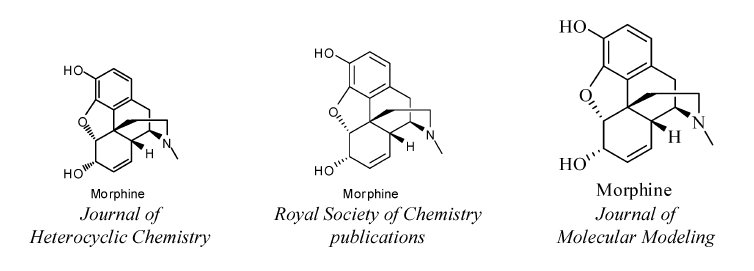
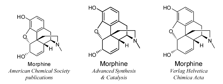
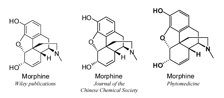
The following nicknames (with capitalization as shown) may be used without further explanation to refer to the structure fragments shown. In all cases, the nicknames should be used to refer only to the specific structures shown, without further substitution and without the presence of further charges, unpaired electrons, or non-natural isotopy.
Authors are welcome to create their own abbreviations as well, but any abbreviations not included in the list below should be defined clearly when they are used (see GR-2.2).
Several of the abbreviations listed below include portions of the text in italics. The italicization shown is the preferred formatting of those abbreviations. However, the corresponding forms without italicization are also acceptable.
| Abbreviation | Full structure |
| Me |  |
| Et |  |
| Pr {†) |  |
| iPr |  |
| Bu |  |
| iBu |  |
| s-Bu |  |
| t-Bu |  |
| Ac (†) |  |
| Ph |  |
| Ms |  |
| Ts (†) |  |
| Cp (&Dsagger;) |  |
(†) The text used by the Ac, Pr and Ts abbreviations is identical to the element
symbols for actinium, praseodymium and tennessine, respectively. Those abbreviations should be
used only in organic contexts where they are unlikely to be mistaken as element symbols.
(‡) The Cp abbreviation may be used only when bonded to a metal atom.
Some very common contracted labels cannot be interpreted with a simple application of valence rules, but also need some implicit charges to be added. Others may represent slightly unusual bonding patterns. The labels shown below, along with their corresponding chalcogen analogs, may be freely used within contracted labels; however, since they all have only a single point of attachment, the textual strings shown below should always be the last (or only) text within a label or within a parenthesized portion of a label. (The central rings and metal atoms in the examples below are provided simply as scaffolds to which these labels are attached. Both left-to-right and right-to-left forms of the label are shown.)
 |  | |
 |  | |
 |  | |
 |  | |
 |  | |
 |  | |
 |  | |
 |  | |
 |  | |
 |  | |
 |  | |
 |  | |
 |  | |
 |  | |
 |  | |
 |  | |
 |  | |
 |  |
1. See, for example: W. A. Warr (Ed.). Chemical Structures 2: The International Language of Chemistry, Springer-Verlag, Berlin (1993).
2. D. Weininger. J. Chem. Inf. Comput. Sci. 30, 237 (1990).
3. H. Helson. Rev. Comput. Chem. 13, 313 (1999).
4. P. C. Fricker, M. Gastreich, M. Rarey. J. Chem. Inf. Comput. Sci. 44, 1065 (2004).
5. A. M. Clark, P. Labute, M. Santavy. J. Chem. Inf. Model. 46, 1107 (2006).
6. IUPAC Chemical Nomenclature and Structure Representation Division. Pure Appl. Chem. 78, 1897 (2006).
7. (a) IUPAC-IUB Joint Commission on Biochemical Nomenclature. Eur. J. Biochem. 186, 429 (1989); (b) IUPAC-IUB Joint Commission on Biochemical Nomenclature. Eur. J. Biochem. 213, 2 (1993); (c) IUPAC-IUB Joint Commission on Biochemical Nomenclature. Pure Appl. Chem. 61, 1783 (1989); (d) R. A. Hill, D. N. Kirk, H. L. J. Makin, G. M. Murphy (Eds.). Dictionary of Steroids, p. xxx, Chapman & Hall, London (1991).
8. A. M. Coghill, L. R. Garson (Eds.). The ACS Style Guide: A Manual for Authors and Editors, American Chemical Society, Washington, DC (2006).
9. R. Pirsig. Zen and the Art of Motorcycle Maintenance, Bantam Books, New York (1974).
10. (a) IUPAC-IUB Joint Commission on Biochemical Nomenclature. Eur. J. Biochem. 79, 1 (1977);
(b) IUPAC-IUB Joint Commission on Biochemical Nomenclature. Biochem. J. 171, 1 (1978).
11. M. Beers (Ed.). The Merck Manual of Medical Information, 2nd home ed., Merck Laboratories, Whitehouse Station, NJ (2003).
12. A. W. Hofmann. Proc. Roy. Inst. 4, 414 (1865).
13. IUPAC. Nomenclature of Inorganic Chemistry, IUPAC Recommendations 2005 (the “Red Book”), N. G. Connelly, T. Damhus, R. M. Hartshorn, A. T. Hutton (Eds.), The Royal Society of Chemistry, Cambridge (2005).
14. IUPAC. Compendium of Chemical Terminology, 2nd ed. (the &147;Gold Book”), compiled by A. D. McNaught and A. Wilkinson, Blackwell Science, Oxford (1997). XML on-line corrected version: (2006–) created by M. Nic, J. Jirat, B. Kosata; updates compiled by A. Jenkins.
15. (a) IUPAC-IUBMB Joint Commission on Biochemical Nomenclature. Adv. Carbohydr. Chem. Biochem. 52, 43 (1997); (b) IUPAC-IUBMB Joint Commission on Biochemical Nomenclature. Carbohydr. Res. 297, 1 (1997); (c) IUPAC-IUBMB Joint Commission on Biochemical Nomenclature. J. Carbohydr. Chem. 16, 1191 (1997); (d) IUPAC-IUBMB Joint Commission on Biochemical Nomenclature. Pure Appl. Chem. 68, 1919 (1996).
16. (a) IUPAC-IUB Joint Commission on Biochemical Nomenclature. Biochem. J. 219, 345 (1984); (b) IUPAC-IUB Joint Commission on Biochemical Nomenclature. Eur. J. Biochem. 138, 9 (1984); (c) IUPAC-IUB Joint Commission on Biochemical Nomenclature. Eur. J. Biochem. 152, 1 (1985); (d) IUPAC-IUB Joint Commission on Biochemical Nomenclature. Int. J. Pept. Protein Res. 24, 84 (1984); (e) IUPAC-IUB Joint Commission on Biochemical Nomenclature. J. Biol. Chem. 260, 14 (1985); (f) IUPAC-IUB Joint Commission on Biochemical Nomenclature. Pure Appl. Chem. 56, 5954 (1984); (g) J. H. Jones (Ed.). Amino Acids and Peptides, Specialist Periodical Report, The Royal Society of Chemistry, 16, 387 (1985); (h) C. Liébecq (Ed.). Biochemical Nomenclature and Related Documents, 2nd ed., p. 39, Portland Press, London (1992).
17. E. Fischer. Ber. Dtsch. Chem. Ges. 24, 1836 (1891).
18. E. Fischer. Ber. Dtsch. Chem. Ges. 24, 2683 (1891).
19. R. B. Grossman. The Art of Writing Reasonable Organic Reaction Mechanisms, 2nd ed., Springer, New York (2003).
20. W. H. Powell, H. Favre (Eds.). Nomenclature of Organic Chemistry, IUPAC Recommendations, Royal Society of Chemistry, in preparation. [See also, Nomenclature of Organic Chemistry, Pergamon Press, Oxford (1979); A Guide to IUPAC Nomenclature of Organic Compounds, Recommendations 1993, R. Panico, W. H. Powell, J.-C. Richer (Eds.), Blackwell Scientific, Oxford, 1993; and corrections in Pure Appl. Chem. 71, 1327 (1999)].
21. IUPAC Organic Chemistry Division. Commission on Nomenclature of Organic Chemistry. Pure Appl. Chem. 70, 143 (1998).
22. IUPAC Organic Chemistry Division. Commission on Nomenclature of Organic Chemistry. Pure Appl. Chem. 71, 513 (1999).
23. IUPAC Organic Chemistry Division. Commission on Nomenclature of Organic Chemistry. Pure Appl. Chem. 71, 587 (1999).
24. (a) IUPAC-IUB Joint Commission on Biochemical Nomenclature. Eur. J. Biochem. 178, 277 (1988); (b) IUPAC-IUB Joint Commission on Biochemical Nomenclature. Pure Appl. Chem. 59, 779 (1987); (c) C. Liébecq (Ed.). Biochemical Nomenclature and Related Documents, 2nd ed., p. 278, Portland Press, London (1992).
25. (a) IUPAC Commission on the Nomenclature of Organic Chemistry (CNOC) and IUPAC-IUB Commission on Biochemical Nomenclature (CBN). Biochem. J. 127, 741 (1972); (b) IUPAC Commission on the Nomenclature of Organic Chemistry (CNOC) and IUPAC-IUB Commission on Biochemical Nomenclature (CBN). Biochem. J.
26. IUPAC. Compendium of Macromolecular Nomenclature (the “Purple Book”), W. V. Metanomski (Ed.), Blackwell Scientific, Oxford (1991).
27. IUPAC Commission on Macromolecular Nomenclature. Pure Appl. Chem. 74, 915 (2002).
28. E. A. Markush. U.S. Patent 1,506,316, Aug. 26, 1924.
29. T. J. Oldfield, R. E. Hubbard. Proteins: Struct., Funct., Genet. 18, 324 (1994).
30. C. M. Duarte, A. M. Pyle. J. Mol. Biol. 284, 1465 (1998).
31. L. Stewart, M. R. Redinbo, X. Qiu, W. G. J. Hol, J. J. Champoux. Science 279, 1534 (1998).
Return to bibliographic home page
Return to chemical nomenclature home page